
Installation guide

Network Infrastructure for EtherNet/IP™
Designing the Infrastructure
4-45
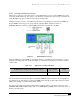
Ethernet Switches Rely on Packet-Switching.
The switch establishes a connection between two segments and maintains the connection just long
enough to send the current packet. Incoming packets, which are part of an Ethernet frame, are
saved to a temporary memory area called a buffer. The MAC address contained in the frame’s
header is read and then compared to a list of addresses maintained in the switch’s lookup table.
Today’s packet-based switches normally use the store-and-forward method of routing traffic. Previously
installed switches may also have used the cut-through, or modified cut-through traffic routing techniques.
The
cut-through method of switching is based on the premise that there is no need for the switch to wait
for the arrival of the complete frame. The switch waits only long enough to read the destination address in
the frame before it begins forwarding the frame to its destination.
A switch using
store-and-forward will save the entire packet to the buffer and run a Cyclic Redundancy
Check (CRC) to locate transmission and storage errors or other problems. If the packet has an error, then
it is discarded. Otherwise, the switch looks up the MAC address and sends the packet on to the
destination node. Some switches combine the two methods by using cut-through until a certain error level
is reached, then changing over to store-and-forward. Very few switches are strictly cut-through since this
provides no error detection.
Modified cut-through (also known as fragment-free) switches are an attempt to offer the best of both
store-and-forward and cut-through switching. In an Ethernet environment, an incoming frame is held until
the first 64 bytes have been received. If the frame is incomplete or corrupt, it can usually be detected
within the first 64 bytes. Therefore, a trade-off between switch latency and error checking is achieved.
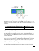
Message Types
There are three types of communication in IP networks: unicast, multicast and broadcast. A unicast
packet is addressed to an individual node, a multicast packet is addressed to a group of nodes, and
a broadcast packet is addressed to all nodes on a network. Each node, regardless of the type of
communication in which it participates, must have a uniquely assigned IP address. When another
node wants to send a unicast packet to this node, it must use this address as a destination address.
When a node wants to send to this node, or a group of nodes, it must use a multicast packet and a
destination address, a specific address selected from the IP multicast address class (class D). When a
node wants to send a broadcast packet addressed to all nodes on the network, it must use, as a
destination address, IP address 255.255.255.255.
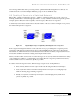
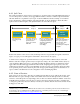
4.8 IGMP Snooping
Internet Group Management Protocol (IGMP) snooping constrains the flooding of multicast traffic by
dynamically configuring the switch interfaces such that multicast traffic is forwarded only to those
interfaces associated with IP multicast devices. In other words, when a multicast message is sent to the
switch, the switch forwards the message only to the interfaces that are interested in this traffic.