
Installation guide

Network Infrastructure for EtherNet/IP™
Designing the Infrastructure
4-42
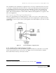
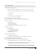
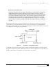
There can be as much as a 45-volt high frequency offset in ground potential between the two ends of a
100-meter (328 ft) cable. This offset can cause noise currents in the shields. Consequently, to eliminate
ground loops, the cable should be grounded at the switch end only as shown in Figure 4-5.
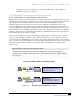
Figure 4-5 Grounding of Cable Shield.
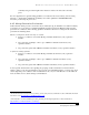
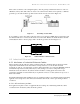
If, for example, a device other than a switch provides a low resistance (<500k ohms) ground at the jack,
the shield should not be connected at the device end of the cable. Rather, the shield should be cut back
and insulated from the connector plug’s shell to break the ground as shown in Figure 4-6.
Figure 4-6 Null Termination of Shielded Cable.
4.5 Industrial Ethernet Connectors
4.5.1 Attributes of Industrial Ethernet Cables
When selecting network cable, the jacket construction must be compatible with any vibration and the
temperature and chemicals in the environment. It is important not to overlook cable electrical
specifications, such as over-temperature, as many off-the-shelf cables do not meet the TIA/EIA standards
at industrial temperatures. Cable jackets may by easily damaged, even at low temperature ranges.
Chemicals can be absorbed into the jackets and wire insulation, causing plastic deterioration and
performance degradation. Sealed media may be required if connectors or cable jackets are exposed to a
harsh environment.
In industrial unshielded cable installations, the use of balanced cables is recommended. If the networking
application is in a high-noise environment, then shielded cable media or fiber-optic cabling should be
considered.
4.5.1.1 Oil-resistant Jackets
If an application requires control of equipment that uses cutting oils or lubricating chemicals, cables
constructed with oil-resistant jackets should be specified.