
Installation guide

Network Infrastructure for EtherNet/IP™
Designing the Infrastructure
4-36
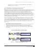
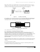
All of the Ethernet data communications equipment can be connected to additional switches and routers
to extend the overall physical network size. The use of fiber-optic cabling along with twisted pair helps
extend the Ethernet network. Switches and routers allow full-duplex operation—they transmit over a
dedicated transmit pair of wires (or channel) and receive over a dedicated receive channel. With full-
duplex, fully switched installations, collisions will be eliminated, allowing Ethernet to be applied to real-
time control applications.
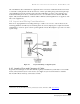
4.4 Layout and Wiring Considerations
There are no rigid guidelines for deciding which type of cable to use or how to route it. However, the
following guidelines can make layout and wiring decisions easier by helping users compare the benefits
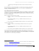
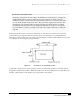
and limitations of various options to their specific application needs. First, Figure 4-3 provides a look at a
typical design.
Figure 4-3 Layout and Wiring of a Typical System.
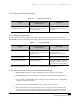
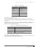
4.4.1 Length of Run and Category of Cable
In general, the total length of each cable channel (segment) in an Ethernet system must not exceed 100
meters (328 ft) between any two active devices. (See Table 4-8.) For more information consult the
EtherNet/IP™ Media Planning and Installation Guide.
16
16
ODVA, Inc., EtherNet/IP™ Media Planning and Installation Guide, Ann Arbor: 2006. www.odva.org