
Installation guide

Network Infrastructure for EtherNet/IP™
Designing the Infrastructure
4-33
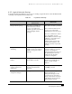
4.2.2 Logical Network Design
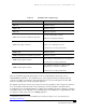
Logical network design (Table 4-5) is a process of creating a logical model of a network infrastructure
consisting of the steps listed in the table below.
Table 4-5 Logical Network Design
Activity Industrial Network with Passive
Infrastructure
EtherNet/IP
Design network topology. This activity is normally not
performed because network
topology is predefined. For
example, proprietary networks use
a fixed and highly-defined
topology.
This activity should be performed.
It is recommended that network
topology be consistent with
plant/enterprise network topology.
It is also recommended to address
here, if applicable, how the
EtherNet/IP network under design
will fit into a typical three-layer
hierarchical model of a
building/campus network with
need for path redundancy, load
balancing, VLANs, and physical
security.
Design a model for addressing
and naming.
A node-addressing model is
usually created. Node naming is
usually not supported in these
networks.
For a non-isolated network this
activity is usually not performed
because node naming and
addressing must be the same as in
the plant/enterprise network to
which this network will be
connected or integrated.
Define switch and router
features.
Not applicable in the context used
in information networks.
This activity should be performed.
Features are normally selected
based on results of traffic
analysis.
Set policies/procedures for
network operation and
maintenance.
Typically performed by plant
engineers and maintenance
personnel.
May be performed by either plant
or IT/MIS personnel.
Develop network security and
management strategies.
Not applicable. This activity should be performed.
Network security and
management strategies should
comply with corporate policies
and procedures and be consistent
with strategies developed for the
plant/enterprise network.