
Installation guide


Network Infrastructure for EtherNet/IP™
Designing the Infrastructure
4-31
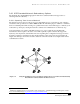
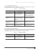
4.1.3 Logical Network Design
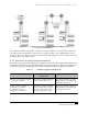
Logical network design is a process of creating a logical model of a network infrastructure consisting of
the steps listed in Table 4-2. Begin by designing a network topology.
Table 4-2 Logical Network Design
Activity Industrial Network with Passive
Infrastructure
EtherNet/IP
Design network topology. This activity is normally not
performed because network
topology is predefined.
This activity should be performed.
Enlist help of IT Dept., system
integrator, or control engineer
familiar with Ethernet systems.
Define IP addressing and
naming.
A node-addressing model is
usually created. Node naming is
usually not supported in these
networks.
This activity should be performed.
May need help from IT Dept.
Develop policies/procedures for
network operation and
maintenance.
Typically performed by plant
engineers and maintenance
personnel.
May be performed by either plant
or IT/MIS personnel.
Define switch and router
features.
Not applicable in the context used
in information networks.
This activity should be performed.
Get IT help if necessary.
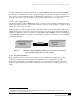
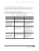
4.1.4 Physical Network Design
Once application requirements have been determined and a logical network design has been achieved, it is
time to design the physical network. See Table 4-3. This stage may be more complex in working with
EtherNet/IP, but it will pay off in the long run if plant-floor connectivity is needed.
Table 4-3 Physical Network Design
Activity Industrial Network with Passive
Infrastructure
EtherNet/IP
Select cable system components
and infrastructure devices.
This activity is equivalent to
selection of the network cable
system components.
This activity must be performed.
System integrators and IT Dept.
may help.