
Installation guide


Network Infrastructure for EtherNet/IP™
Planning the Infrastructure
3-23
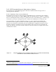
concept is similar to the “Change of State” messaging found in CIP. An event, in this case an error,
triggers a message to a specific device, in this case a trap. This “report by exception” approach limits
Ethernet network management traffic, allowing greater network bandwidth to be used for control.
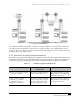
3.5.3 Network Management and Web-based Management Software
Many vendors offer network management software that uses SNMP, Bootstrap Protocol (BootP), and
accessed MIB data to allow an operator to view the status of the entire network. It also allows the IP
addresses to be loaded into the devices. This overview of the installation can be used to identify problem
areas during startup or on an ongoing basis. Detailed information about the devices may also be accessed.
Many devices have an integrated Web-server that allows SNMP data to be accessed using standard
Internet browsers. The combination allows problem areas to be identified using network management
software with the Internet browser to “zoom in” on the device’s web page(s) for access to detailed
information or settings. Some devices also include embedded data sheets or user manuals that can be
accessed.
3.6 Isolated vs. Integrated Networks
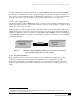
Historically, device-level networks have been “isolated” from one another. A single controller, such as a
PLC or PC, is the “master” of a small network of nodes, such as I/O blocks, variable frequency drives
(VFDs), barcode readers, servo drives, and so on. This small control network does not have a physical
connection to any other network other than through the master PLC or PC. As such, communications
between these device-level networks require a separate network port on the PLC or PC and also require
programming in the controller to send and receive data. In this way, the network communications from
machine to machine, from cell to cell, and throughout a manufacturing campus have been isolated to only
what was needed for the specific connected devices.
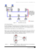
These isolated networks, while very effective at providing distributed control, do not provide the
“seamless” connectivity that industrial Ethernet offers. The ability to connect and communicate between
the business system networks and the plant-floor networks via industrial Ethernet provides a huge
opportunity to reduce work-in-process inventory, improve throughput, find manufacturing bottlenecks,
increase uptime, and improve customer service. The “integrated network,” while providing these
manufacturing improvement opportunities, demands a conscientious effort at an overall network design
and layout for an entire facility. The benefit of Ethernet is that it can be scaled, from small original
equipment manufacturer (OEM) machine control applications, to integrated manufacturing lines. As the
applications become more complex, the quantity, type, and functionality of the required infrastructure
components also grows. (See 6 Infrastructure Application Scenarios for more information.)
Typically, manufacturing and OEM control engineers can achieve the goals of a good industrial Ethernet
network design by using robust industrial Ethernet components. First, the industrial Ethernet electronics
and cabling systems should implement full-duplex switching technology, follow proper Category 5e (or
higher) twisted-pair and fiber installation techniques, and address the environmental conditions present
around the equipment. Next, using the proper equipment and building industrial Ethernet control
networks in a “managed network” scheme, manufacturing and OEM control engineers can achieve
machine control objectives while adding the benefits of total plant network integration. Finally, when
integrated networks with industrial Ethernet are used, new requirements such as security and network
traffic routing can arise. Additional “higher-level” network equipment and networking techniques may be
required to meet these needs.