Network Infrastructure for EtherNet/IPTM: Introduction and Considerations
Network Infrastructure for EtherNet/IP™ Publication Number: PUB00035R0 Copyright © 2007 Open DeviceNet Vendor Association, Inc. (ODVA). All rights reserved. For permission to reproduce excerpts of this material with appropriate attribution to the author, please contact ODVA at: ODVA, Inc. 4220 Varsity Drive, Suite A Ann Arbor, MI 48108-5006 USA Phone +1 734.975.8840 Fax +1 734.922.0027 E-mail odva@odva.org Web www.odva.
Network Infrastructure for EtherNet/IP™ Note from the Publisher The application of Ethernet and Internet technologies is permeating every aspect of manufacturing automation today—control, safety, configuration and diagnostics, synchronization and motion, and information. To realize the benefits of these technologies, the network infrastructure is critical and represents a long-term investment for users that requires thorough analysis of performance requirements along with technology choices and trends.
Network Infrastructure for EtherNet/IP™ Contents Preface.......................................................................................................................................................viii 1 INDUSTRIAL ETHERNET… NOT JUST ANOTHER FIELDBUS ........................................1-1 1.1 Industrial Networks ................................................................................................................................... 1-1 1.2 Introduction to EtherNet/IP ..........
Network Infrastructure for EtherNet/IP™ 3.5.2 Traps.................................................................................................................................................. 3-22 3.5.3 Network Management and Web-based Management Software......................................................... 3-23 3.6 Isolated vs. Integrated Networks ............................................................................................................. 3-23 3.6.1 Security Issues...........
Network Infrastructure for EtherNet/IP™ 4.8.3 Immediate-Leave Processing............................................................................................................. 4-48 4.9 Quality of Service in a Switched Network............................................................................................... 4-49 4.9.1 QoS Flow........................................................................................................................................... 4-50 4.9.
Network Infrastructure for EtherNet/IP™ 7.1.3 Fiber-Optic Connectors ..................................................................................................................... 7-82 7.2 Cabling Considerations: Twisted-Pair vs. Fiber-Optic Cable.................................................................. 7-83 7.2.1 When to Use Shielded Twisted-Pair Cabling .................................................................................... 7-83 7.2.2 Terminating Copper Cable .............
Network Infrastructure for EtherNet/IP™ Preface About This Publication Advances in Ethernet technology and reduced component costs are fueling the growth of Ethernet in plant floor networks. EtherNet/IP™, the adaptation of the Common Industrial Protocol™ (CIP™) provides users with the tools to deploy standard Ethernet technology for manufacturing applications while enabling Internet and enterprise connectivity… anytime, anywhere.
Network Infrastructure for EtherNet/IP™ 1 Industrial Ethernet… Not Just Another Fieldbus Using the Common Industrial Protocol (CIP™), EtherNet/IP provides the backbone for a completely open, vendor-neutral communication network for the full range of manufacturing applications, and can integrate these applications with one another and the enterprise.
Network Infrastructure for EtherNet/IP™ EtherNet/IP: • offers producer-consumer services that enable users to control, configure, and collect data from over a single network or to use the network as a backbone for multiple distributed networks. • provides robust physical layer options for industrial environments and includes the use of sealed RJ-45 and M12-4 “D” Coded connectors.
Network Infrastructure for EtherNet/IP™ receiving devices can consume this data simultaneously. Implementation of this model in CIP is supported by the Internet Protocol (IP) multicast service which, in its turn, is supported by the Ethernet multicast service. The primary benefit of a producer-consumer network is its more efficient use of bandwidth. When a message is produced on the network, it is identified not by its destination address, but by its connection ID.
Network Infrastructure for EtherNet/IP™ 1.2.2 Infrastructure for EtherNet/IP Applications A communication network can be viewed as a utility for providing services that allow devices, or humans operating these devices, to exchange information. A typical modern communication network is functionally a mix of computer, telecommunication, and broadcast networks capable of supporting voice, data, video, and image communication.
Network Infrastructure for EtherNet/IP™ 2 Understanding the Basics of Network Protocols The following discussion includes information on the TCP/IP suite, focusing on the Transmission Control Protocol (TCP), the Internet Protocol (IP) and the User Datagram Protocol (UDP). The OSI Model provides a conceptual framework for communication between computers, but the model itself is not a method of communication. Actual communication is made possible by using communication protocols.
Network Infrastructure for EtherNet/IP™ 2.1 The TCP/IP Suite EtherNet/IP incorporates the TCP/IP suite, utilizing TCP for explicit messaging and UDP for implicit or I/O messaging. These widely adopted protocols are implemented at the network layer (IP) and the transport layer (UDP and TCP) of the OSI Model, and are the basic networking technology for EtherNet/IP.
Network Infrastructure for EtherNet/IP™ The following descriptions summarize the TCP packet fields. • Source Port and Destination Port: Identifies the source and destination processes that are to receive TCP services. • Sequence Number: Typically specifies the number assigned to the first byte of data in the current message. • Acknowledgment Number: Contains the sequence number of the next byte of data the sender expects to receive.
Network Infrastructure for EtherNet/IP™ IP addressing supports three different network classes. Class A networks are intended mainly for use with a few very large networks because they provide only 8 bits for the network address field. Class B networks allocate 16 bits, and Class C networks allocate 24 bits for the network address field. Class C networks provide only 8 bits for the host field, so the number of hosts per network may be a limiting factor.
Network Table 2-2 Infrastructure for EtherNet/IP™ Subnet Masks Dot-decimal Address Binary Full Network Address 192.168.5.10 11000000.10101000.00000101.00001010 Subnet Mask 255.255.255.0 11111111.11111111.11111111.00000000 Network Portion 192.168.5.0 11000000.10101000.00000101.00000000 Subnet masks have ones in all bits except those that specify the host field. For example, the subnet mask that specifies 8 bits of subnetting for Class A address 34.0.0.0 is 255.255.0.0.
Network Infrastructure for EtherNet/IP™ Unlike the TCP, UDP adds no reliability, flow-control, or error-recovery functions to IP. Because of UDP’s simplicity, UDP headers contain fewer bytes and, therefore, consume less network overhead than TCP. UDP is useful in applications where efficiency of data delivery takes precedence over verification of data delivery, such as in cases where a higher-layer protocol might provide error and flow control.
Network Infrastructure for EtherNet/IP™ processing systems. Office network examples are file, print, mail, and database servers. Examples related to EtherNet/IP networks are DHCP/BOOTP, DNS, and web servers. Publish-subscribe communication is a one-to-many model. In these systems, devices subscribe to data they need and publish information they produce.
Network Infrastructure for EtherNet/IP™ 3 Planning the Infrastructure The most significant differences between industrial Ethernet networks and device-level networks are presented here with information on how industrial EtherNet/IP networks are designed and built. Open device-level networks have been a key element of building modular manufacturing systems. The networks’ quick response times, low connect costs, and simplicity fuel their growth.
Network Infrastructure for EtherNet/IP™ These networks can connect more than 60 devices with communication cable without using any other components. Bus extenders or bridges increase the network length or add layout flexibility, but they are optional. Industrial Ethernet uses “star” topology to connect infrastructure components to each other and to end devices.
Network Infrastructure for EtherNet/IP™ network’s response time, infrastructure components and addressing techniques provide connectivity while segregating plant-floor traffic. 3.2 Ethernet System Components Industrial Ethernet systems require various infrastructure components to connect all the segments together. These include hubs, switches (especially managed switches), media converters, cables, and routers.
Network Infrastructure for EtherNet/IP™ on the manufacturing floor. In fact, the use of Ethernet switches is the preferred means of Ethernet interconnect of EtherNet/IP systems. Typical industrial switches can connect four or more network segments or Ethernet devices. Each of these connections (ports) typically supports both 10-Mbps and 100-Mbps data rates. Many of the newer switches will support 1-Gbps data rates as well. 3.2.
Network Infrastructure for EtherNet/IP™ Managed Switches Managed switches provide the basic switching capabilities of unmanaged switches, plus they offer additional diagnostic or traffic-management functions. In essence, a managed switch is configured or tailored for a particular part of the overall application. The different switches in an application can each have different configurations that the user must maintain.
Network Infrastructure for EtherNet/IP™ 3.3 Ethernet Cabling Systems New Ethernet installations are based on twisted-pair and fiber-optic cables. The following presents general guidelines and an overview of cabling schemes. The use of industrial grade Ethernet cable is critical for withstanding exposure to harsh environments. 3.3.1 Star Topology: The Standard Approach Industrial Ethernet systems are laid out in a point-to-point cabling scheme with one cable used for each device being connected.
Network Infrastructure for EtherNet/IP™ wires) and four twisted-pair (eight wires) UTP cables. Two twisted-pair cables support network speeds of 10 Mbps as well as the 100-Mbps. Industrial Ethernet systems with 1-Gbps speeds use four twisted-pair cables with a maximum cable length of 100 meters (328 ft). Pre-configured Category 5e (CAT 5e) cables are available in required lengths. Field terminations may require manual work with crimping tools, bulk cable, and connectors.
Network Infrastructure for EtherNet/IP™ Recommended Cable Practice Different cable types can be distinguished through the use of different colored outer cable jackets. Most infrastructure components automatically compensate for the type of device connected. This is known as auto-crossover or auto MDI/X capability. There are two classes of Ethernet devices: Data Communications Equipment (DCE) refers to infrastructure components, and Data Terminal Equipment (DTE) refers to control devices.
Network Infrastructure for EtherNet/IP™ communications is used. Cable lengths of 2000 meters (6562 ft) are possible using multimode fiber in full-duplex, 100-Mbps applications. The use of pre-terminated glass fiber-optic cables is recommended. Fiber-optic cables are terminated using SC, ST, or MTRJ connectors. Like twisted-pair wiring, the use of half-duplex communications has additional restrictions as to how many hubs can be used between the sending and receiving devices.
Network Infrastructure for EtherNet/IP™ Destination Address (DA) is the target MAC address for which the packet of data is intended. Setting the first bit to a “1” in the DA field, indicates a packet of data for multiple destinations. This enables an Ethernet device to transmit one packet that can be received by multiple other devices. There are a number of different types of Ethernet packets that can be sent and received on an Ethernet network.
Network • Infrastructure for EtherNet/IP™ DHCP - Dynamic Host Configuration Protocol This is a protocol to allow a device, acting as a DHCP server, to assign 4-byte IP addresses to devices connected to the network. • DNS - Domain Name Services This protocol searches for resources on a TCP/IP network using a database connected to the TCP/IP network. It makes correlations between computer names, their 4-byte IP addresses, and the resources and information available in the network.
Network Infrastructure for EtherNet/IP™ concept is similar to the “Change of State” messaging found in CIP. An event, in this case an error, triggers a message to a specific device, in this case a trap. This “report by exception” approach limits Ethernet network management traffic, allowing greater network bandwidth to be used for control. 3.5.
Network Infrastructure for EtherNet/IP™ 3.6.1 Security Issues Firewalls are important to the security of integrated networks. Routers and switches may also be configured to contribute to network security. 3.6.1.1 Firewalls A firewall is a software and hardware solution that acts as a barrier to protect a network from outside intruders when connected to a wide area network (WAN), such as an enterprise network or the Internet. Any plant-floor information (e.g.
Network Figure 3-3 Infrastructure for EtherNet/IP™ VLAN-tagged Frames are Identified when the MAC Finds the LAN Type Value in the Normal Length/Type Field Location. The VLAN header contains a Tag Control field that defines the transmission priority (0 to 7, where 7 is the highest) and a VLAN ID that identifies the particular VLAN over which the frame is to be sent. These provide the means to expedite time-critical network traffic.
Network Infrastructure for EtherNet/IP™ 3.8.1 IEEE Standard Network Redundancy Options The Spanning Tree and Trunking/Aggregation methods are standard, multi-vendor approaches to achieving network redundancy. 3.8.1.1 Spanning Tree Protocol Method The Spanning Tree Protocol (STP) is a Layer 2 (data link layer) protocol designed to run on bridges and switches. The specification for STP is IEEE Std 802.1D.
Network Infrastructure for EtherNet/IP™ The Rapid Spanning Tree (RSTP) specification (originally IEEE Std 802.1W, now included in IEEE Std 802.1D) is an enhancement over the original Spanning Tree specification. It allows for faster recovery times (a few seconds) than Spanning Tree. In Spanning Tree applications, recovery times typically range from 30 to 60 seconds. Large and complex topologies may result in minutes of recovery time. 3.8.1.2 Link Aggregation The Link Aggregation method (IEEE Std 802.
Network Figure 3-6 Infrastructure for EtherNet/IP™ Ring Redundancy Topology. 3.8.3 Dual Homing The dual homing approach is typically used to achieve redundancy between routers or network layer (Layer 3) switches that have router-level functions. (See 4.11 Multilayer Ethernet Switches for more information.) In addition to a simple hub-and-spoke network where a remote router is connected to a single distribution router, the remote router can be dual-homed to two or more distribution routers.
Network Infrastructure for EtherNet/IP™ 4 Designing the Infrastructure Network design is a methodical, step-by-step process. It includes the top-down process of mapping out the network infrastructure required for an application. This systematic process focuses on the application, technical objectives, and business goals.
Network Figure 4-1 Infrastructure for EtherNet/IP™ Comparison of Isolated and Integrated EtherNet/IP Networks. (Courtesy of General Motors.) An isolated network has no immediate, continuous connection with the rest of the plant floor network or the enterprise network. Typically, it will connect to a supervisory PC or node, which will then act as a gateway to filter out connections from/to the main network. The design process for an isolated network is broken into three steps, which follow. 4.1.
Network Infrastructure for EtherNet/IP™ 4.1.3 Logical Network Design Logical network design is a process of creating a logical model of a network infrastructure consisting of the steps listed in Table 4-2. Begin by designing a network topology. Table 4-2 Activity Logical Network Design Industrial Network with Passive Infrastructure EtherNet/IP Design network topology. This activity is normally not performed because network topology is predefined. This activity should be performed.
Network Infrastructure for EtherNet/IP™ 4.2 Non-Isolated EtherNet/IP Networks A non-isolated network as shown in Figure 4-1 is integrated with the rest of the plant floor network and can communicate upwards to the enterprise network. Since there are more integration concerns (e.g., working with corporate IT), initial design work will be necessarily more involved. The design steps follow. 4.2.
Network Infrastructure for EtherNet/IP™ 4.2.2 Logical Network Design Logical network design (Table 4-5) is a process of creating a logical model of a network infrastructure consisting of the steps listed in the table below. Table 4-5 Activity Design network topology. Logical Network Design Industrial Network with Passive Infrastructure This activity is normally not performed because network topology is predefined. For example, proprietary networks use a fixed and highly-defined topology.
Network Infrastructure for EtherNet/IP™ 4.2.3 Physical Network Design Table 4-6 Activity Physical Network Design Industrial Network with Passive Infrastructure Select cable system components and infrastructure devices. This activity is equivalent to selection of the network cable system components. EtherNet/IP This activity must be performed. System integrators and IT Dept. may help. 4.2.
Network Infrastructure for EtherNet/IP™ information wherever and whenever it is needed by qualified users, such as plant and maintenance engineers or managers. 4.3 EtherNet/IP Infrastructure Design Issues 4.3.1 Full-Duplex vs. Half-Duplex Implications Ethernet is based on Carrier Sense Multiple Access/Collision Detect (CSMA/CD) technology.
Network Infrastructure for EtherNet/IP™ All of the Ethernet data communications equipment can be connected to additional switches and routers to extend the overall physical network size. The use of fiber-optic cabling along with twisted pair helps extend the Ethernet network. Switches and routers allow full-duplex operation—they transmit over a dedicated transmit pair of wires (or channel) and receive over a dedicated receive channel.
Network Table 4-8 Infrastructure for EtherNet/IP™ Maximum Cable Lengths by Type Cable Maximum Segment Length 10Base-T 100 meters (328 ft) 100Base-TX 100 meters (328 ft) 10Base-FL 2000 meters (6562 ft) 412 meters (half-duplex) (1352 ft) 100Base-FX (62.5 micron multimode glass fiber) 2000 meters (full-duplex) (6562 ft) 412 meters (half-duplex) (1352 ft) 100Base-FX (single-mode fiber) 15 km or more (full-duplex) (6.2 mi) Consult vendor for cable-specific limits.
Network Infrastructure for EtherNet/IP™ 4.4.2 Cable Routing A proper cable routing plan is essential. EtherNet/IP or any network cables should not be routed near equipment that generates strong electric or magnetic fields.
Network Infrastructure for EtherNet/IP™ continuity along its entire length. It also must be bonded to the enclosure at the entry point. For more information on general wiring guidelines, see Industrial Automation Wiring and Grounding Guidelines18 and the Telecommunications Industry Association publication ANSI/TIA/EIA-607, Grounding and Bonding Requirements.19 4.4.5 Wiring External to Enclosures Cables that run outside protective enclosures may be relatively long.
Network Table 4-9 Infrastructure EtherNet/IP™ Outside Wiring Voltage Level 0-100 V for Minimum Distance 7.6 cm (3 in.) 101-200 V 10.2 cm (4 in.) 201-300 V 12.7 cm (5 in.) 301-400 V 15.2 cm (6 in.) 401-500 V 17.8 cm (7 in.) 4.4.6 Wiring Inside Enclosures Cable sections that run inside protective equipment enclosures are relatively short. As with wiring external to enclosures, maximum separation between Ethernet cables and Category-1 conductors should be maintained.
Network Infrastructure for EtherNet/IP™ Grounding of Shielded Cables Shields play an important role in providing noise immunity for systems. However, an improperly installed shielded cable can cause problems due to voltage offsets in a grounding system. To minimize the effects of ground offsets, the shield should be isolated at one end of the cable. In this case, the shield should be isolated at the device. The ground can be applied at the switch or other infrastructure component.
Network Infrastructure for EtherNet/IP™ There can be as much as a 45-volt high frequency offset in ground potential between the two ends of a 100-meter (328 ft) cable. This offset can cause noise currents in the shields. Consequently, to eliminate ground loops, the cable should be grounded at the switch end only as shown in Figure 4-5. Figure 4-5 Grounding of Cable Shield.
Network Infrastructure for EtherNet/IP™ 4.5.1.2 Plenum-rated Cables Plenum installations require special material compounds in the makeup of cables. If an application requires cables to be run in air-handling space, plenum-rated cables should be used, and may be required by local electrical codes. (Often local electrical codes are concerned with voltage and current levels for power wiring in a heated duct.
Network Infrastructure for EtherNet/IP™ appropriate segment. Since any segment contains only a single node, the frame only reaches the intended recipient. Before switches were used, Ethernet was a half-duplex network. Thanks to managed and unmanaged switches, Ethernet can be a full-duplex network. Switched Networks and Full-Duplex Ethernet In a switched network, nodes only communicate with the switch and never directly with each other.
Network Infrastructure for EtherNet/IP™ Ethernet Switches Rely on Packet-Switching. The switch establishes a connection between two segments and maintains the connection just long enough to send the current packet. Incoming packets, which are part of an Ethernet frame, are saved to a temporary memory area called a buffer. The MAC address contained in the frame’s header is read and then compared to a list of addresses maintained in the switch’s lookup table.
Network Infrastructure for EtherNet/IP™ IGMP Snooping The Internet Group Management Protocol is very important because it reduces the load of traffic traversing through the network. It also relieves the hosts from processing frames that are not needed. In the producer-consumer model used by EtherNet/IP, IGMP snooping limits unnecessary traffic from the producing I/O, such that it only reaches the devices that consume that data.
Network Infrastructure for EtherNet/IP™ 4.8.1 Joining a Multicast Group When a host connected to the switch wants to join an IP multicast group, it sends an IGMP join request, specifying the IP multicast group it wants to join. When the switch receives this message, it adds the port to the IP multicast group port address entry in the forwarding table. In Figure 4-7, Host 1 wants to join multicast group 224.1.2.
Network Figure 4-8 Infrastructure for EtherNet/IP™ Second Host Joining a Multicast Group. If another host (for example, Host 4 in Figure 4-8) sends an IGMP join message for the same group, the CPU receives that message and adds the port number of Host 4 to the multicast forwarding table as shown in Table 4-12. Table 4-12 Updated Multicast Forwarding Table Entry Updated Multicast Forwarding Table Destination Address Type of Packet Ports 0100.5E01.0203 !IGMP 1, 2, 5 4.8.
Network Infrastructure for EtherNet/IP™ leave message. Immediate-leave processing ensures optimal bandwidth management for all hosts on a switched network, even when multiple multicast groups are in use simultaneously. 4.
Network Infrastructure for EtherNet/IP™ 4.9.1 QoS Flow The common definition of QoS in Layer 2 switches is to prioritize native encapsulated Ethernet frames or to honor 802.1p Class of Service (CoS) tagged Ethernet frames.20 However, advanced QoS mechanisms take this definition a step further. Layer 2 QoS on advanced Ethernet switches entail up to four distinct stages: classification, policing, marking, and queue/schedule.
Network Infrastructure for EtherNet/IP™ Figure 4-11 depicts an Ethernet frame tagged with an 802.1Q field, which consists of a two-byte Ethertype and a two-byte 802.1Q Tag. Within the two-byte tag are the user priority bits (known as 802.1p CoS bits). Figure 4-11 Details of Ethernet Frames and IP Packet. 4.9.3 Priority Mechanisms For any QoS services to be applied to data, there must be a way to “tag” or prioritize an IP packet or an Ethernet frame. The Layer 2 802.
Network Infrastructure for EtherNet/IP™ 4.10 Virtual Local Area Networks As networks have grown in size and complexity, many companies have turned to Virtual Local Area Networks (VLANs) to provide a means for structuring this growth logically. Basically, a VLAN is a network that is created logically, using software, as opposed to physical cabling.
Network 4.10.1 Infrastructure for EtherNet/IP™ VLAN Trunking VLANs can span across multiple switches and you can have more than one VLAN on each switch. For multiple VLANs on multiple switches to be able to communicate via a single link between the switches, trunking is needed. Trunking is the technology that allows information from multiple VLANs to be carried over just one link between switches. Switches use VLAN trunking protocols to communicate VLAN configuration information between them.
Network Infrastructure for EtherNet/IP™ 4.11 Multilayer Ethernet Switches A multilayer Ethernet switch performs the traditional function of a Layer 2 device but also can perform functions based on information from other layers of the networking stack. For example, a multilayer switch can inspect the IP information encapsulated in an Ethernet frame and perform routing decisions based on it (Layer 3 switching), assign a given priority to the frame (QoS), and deny or permit access (security).
Network Infrastructure for EtherNet/IP™ Layer 3 switching operates at the network layer. It examines packet information and forwards packets based on their network-layer destination addresses. Layer 3 switching also supports router functionality. As routers operate at Layer 3 of the OSI Model, they can adhere to and formulate a hierarchical addressing structure.
Network Infrastructure for EtherNet/IP™ 4.12 Achieving Deterministic Behavior Different mechanisms can be implemented to achieve reliable and deterministic behavior on a network. Scale and criticality are two key factors for determining when to implement such mechanisms. Just as a back country road often can effectively move traffic and manage the potential for collisions with a single lane, traffic in larger metropolitan areas generally demands multi-lane, multi-level highways.
Network Infrastructure for EtherNet/IP™ It is important to keep in mind that everyone is working for the same team and toward the same goals. This spirit of cooperation is a prerequisite to achieving an effective plant-floor-to-enterprise information system. Business leaders also must realize that while engineers from both disciplines share the same ideals—performance, speed, and security—they tend to employ different problem-solving methods to achieve the same ends.
Network Infrastructure for EtherNet/IP™ 5 Deploying the Network EtherNet/IP networks can be tested using relatively inexpensive equipment and software. There are some quick and easy methods of assuring that EtherNet/IP cables and connectors are providing connectivity. Deployment also involves configuring the system for EtherNet/IP traffic.
Network Infrastructure for EtherNet/IP™ cabinets to protect them from shop-floor environments. For critical applications, the use of more durable sealed connectors will stand up to the rigors of plant-floor environments. Testing is easily done with commercially available hand-held network testers. Special adapters may be necessary for sealed connectors.
Network Infrastructure for EtherNet/IP™ 5.1.2 Ping Checks for TCP/IP Continuity If proper wiring between two devices has been verified, another built-in diagnostic tool that can be used is the ping. Like the link LEDs built into EtherNet/IP devices, ping is built into TCP/IP software. A ping is basically an Internet Control Message Protocol (ICMP) echo request and echo response between two TCP/IP devices. As EtherNet/IP uses TCP/IP, EtherNet/IP devices may support ping.
Network Infrastructure for EtherNet/IP™ Linux and UNIX computers can send pings from the command line as well, but if a count is not specified, the computer will continue to send pings until a terminate command is given by hitting [Ctrl-c]. To specify a number of pings under UNIX or Linux, type [ping –c x 192.168.25.25] where x is the number of pings to be sent to the address that follows. Ping can be used to validate connections and IP addresses and to help determine where connections are failing.
Network Infrastructure for EtherNet/IP™ The IP address of the switch can generally be configured using a console cable directly connected to the device. Alternatively, a Dynamic Host Configuration Protocol (DHCP) or Bootstrap (BootP) server can be used. Managed switches also allow for remote management of the network.
Network Infrastructure for EtherNet/IP™ office networks, where IP multicast traffic is generated sporadically and with much lower packet rates. A growing exception to this traffic profile may be in the area of multimedia audio and video conferencing applications. EtherNet/IP Specification Tip In accordance with The EtherNet/IP™ Specification, a message producer can send data encapsulated in either an IP unicast or IP multicast packet. 5.2.
Network Infrastructure for EtherNet/IP™ 10.88.80.110 and the IP Source Address 10.88.80.100. The packet rate will be 200 packets per second, consisting of 100 multicast and 100 unicast packets per second. 5.2.3 IP Multicast Traffic in EtherNet/IP Networks To satisfy the performance requirements of the implicit messaging traffic, the following is recommended: • EtherNet/IP network infrastructure should be based on Ethernet switching technology. • Micro-segmentation should be used.
Network Infrastructure for EtherNet/IP™ 6 Infrastructure Application Scenarios Regardless of the specific application, all networks require a design that deals with multicast traffic to meet the needs of real-time control. EtherNet/IP supports both the time-critical (implicit) and non-time-critical (explicit) message transfer services of CIP.
Network Infrastructure for EtherNet/IP™ Within each of these four network types, recommendations can be made regarding the types of active infrastructure components (switches, routers, etc.) and the key functions needed to balance real-time performance with data connectivity requirements. Appendix A Recommendations for Ethernet Switches in EtherNet/IP Systems complements this chapter by summarizing the recommended switch functions for each of the four system types. 6.
Network Infrastructure for EtherNet/IP™ 6.1.2.2 Varying Sensitivity by Device Type Certain devices, such as Windows-based PCs/workstations, may have an extra sensitivity to multicast traffic. There can be significant variance in sensitivity between the same devices from different vendors, and between different devices from the same vendor.
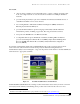
Network Infrastructure for EtherNet/IP™ 6.2.1 Systems with Low Device Counts In the example shown in Figure 6-1, IP multicast traffic is produced by I/O devices and consumed by the programmable controller. Here, IP multicast traffic produced by I/O1 will be sent to all devices connected to the switch, including I/O2 through I/O5 and the workstation. Workstation Programmable Controller 8-port Ethernet Switch I/O1 Figure 6-1 I/O5 Isolated Network with One Controller.
Network Infrastructure for EtherNet/IP™ When using unmanaged switches, follow these guidelines: Calculate or test the maximum multicast traffic load for each device. For each device, ask the vendor for the maximum unwanted multicast packets per second rate that the device can withstand while maintaining the desired RPI rate. Be sure to use the configuration with the largest I/O count or most time-critical configuration.
Network Infrastructure for EtherNet/IP™ Confirm that the total unwanted multicast traffic value is less than each devices’ maximum unwanted multicast traffic rate. If it is greater, add managed switches. Adding managed switches reduces the multicast domain as shown in Figure 6-3. Figure 6-3 Use Managed Switches to Reduce the Size of a Multicast Domain. This is also a key concept for end users who may be interconnecting multiple OEM machines from one or more vendors.
Network Infrastructure for EtherNet/IP™ multicast messaging. Disabling multicast messages allows the use of unmanaged switches. This is most effective for systems with one consumer. In the systems described in these examples, a certain amount of the workstation’s and remote I/O devices’ computing power is used to filter the unwanted traffic.
Network Workstation Infrastructure for EtherNet/IP™ Programmable Controller 8-port Switch 8-port Switch 1 Producer 1 Figure 6-5 8-port Switch 4 Producer 6 Producer 19 Producer 24 Isolated Network with One Controller. EXAMPLE 3 In the example shown in Figure 6-5, IP multicast traffic is produced by 24 producers, remote I/O rails and/or drives, and is consumed by the programmable controller.
Network • Infrastructure for EtherNet/IP™ If workstation and remote I/O performance are affected, a switch with IGMP snooping should be used. In isolated networks, one of the switches will be required to have the IGMP query function to manage the multicast process as shown in Figure 6-6.
Network Infrastructure for EtherNet/IP™ In this example, if producer traffic is unicast instead of multicast, then switch 4 will process 600 packets per second, switch 3 will process 1200 packets per second, switch 2 will process 1800 packets per second, and switch 1 will process 2400 unicast packets per second.
Network Infrastructure for EtherNet/IP™ Figure 6-9 depicts the logical view of the system set up as two VLANs. Here, ports 1, 3, 4, 5, and 6 belong to VLAN 1; ports 2, 7, 8 and 9 belong to VLAN 2. For more distributed applications, VLANs can also be implemented across multiple switches.
Network Infrastructure for EtherNet/IP™ 6.4 Enterprise-Connected and Integrated Control Systems There are often requirements for enterprise or plant-wide networks to selectively access control system data. Higher level plant systems often contain servers used to download the control programs necessary to reconfigure flexible manufacturing systems.
Network Infrastructure for EtherNet/IP™ 6.4.2 Networks Integrated with Routers (or Layer 3 Switches) An enterprise-integrated EtherNet/IP network is fully integrated into the enterprise network infrastructure. This type of interconnection results in a single, integrated network. The addressing practices, security policies, network management techniques, and “change control” procedures of the enterprise network and the control system portions of that network must be harmonized. 6.4.
Network Infrastructure for EtherNet/IP™ 6.4.3.2 Interlock Connections An interlock connection is used if there is implicit message traffic traversing the backbone network. As shown in Figure 6-12, the traffic being passed is real-time implicit, supervisory, programming, monitoring, and so forth. There is real-time data being passed. There is no CIP gateway in use. The backbone is connected directly to the plant-floor network infrastructure.
Network Infrastructure for EtherNet/IP™ 6.5 Application Summary Characterizing network traffic on EtherNet/IP helps determine which type of network will provide the best balance of performance and installed cost. The recommendations provided here are aimed at optimizing network—and ultimately control system—performance. They are based on the use of switches with the increasing levels of functionality needed to handle more devices with more traffic and short, implicit I/O control response times.
Network Infrastructure for EtherNet/IP™ 7 Selecting Components This detailed look at the component features behind successful EtherNet/IP networks can be used as a checklist to help ensure the chosen components can provide the right functionality and withstand their industrial environments. Included here are connectors, wire and fiber-optic cabling, switches, routers, and equipment housings. 7.
Network Figure 7-1 Figure 7-2 Infrastructure for EtherNet/IP™ RJ-45 Sealed Connector. RJ-45 Sealed Plug.
Network Infrastructure for EtherNet/IP™ 7.1.2 M12 “D”-Coded Connector for EtherNet/IP The EtherNet/IP™ Specification also allows the use of the four-pin, “D”-coded M12 connector for IP65and IP67-rated environments. This device is shown on the left in Figure 7-3 and is the pin-and-socket style connector for EtherNet/IP. It will be familiar to many engineers from its standard version, which is in widespread use in industrial applications, such as with sensors and actuators.
Network Infrastructure for EtherNet/IP™ 7.2 Cabling Considerations: Twisted-Pair vs. Fiber-Optic Cable Deciding whether to use fiber-optic cable or twisted-pair copper cable depends on specific application and environmental requirements. Users need to compare capabilities to find the right match for their requirements. • Fiber-optic cable is inherently impervious to noise from electrical and magnetic fields.
Network Infrastructure • Electrostatic processes • High-current devices (greater than 100 amps) for EtherNet/IP™ 7.2.2 Terminating Copper Cable Termination of copper cables is a simple process. Copper cable termination tools and supplies are available from many convenient sources. Figure 7-5 shows a typical RJ-45 Ethernet connector. Studies have shown, however, when communicating at 100 Mbps, poor cable terminations can increase the number of retransmissions. This will reduce system throughput.
Network Infrastructure for EtherNet/IP™ 7.2.3 When to Use Fiber-Optic Cabling Fiber should be considered when the required length is greater than 100 meters (328 ft) between two devices. If an application creates high magnetic and electric fields, fiber should be considered. Applications such as magnetic galvanizing annealing furnaces and high-power RF cross-linking machines are ideally suited to the use of fiber-optic cabling. 7.2.
Network Infrastructure for EtherNet/IP™ 7.2.6 Terminating Fiber-Optic Cable Proper termination of fiber-optic cable can be a difficult process. If not performed properly, poor connections can reduce the distance capability of the system. Tools are available to help judge the quality of the termination and the fiber-optic cables. Fiber connectors should only be installed by trained personnel. The channel performance can be severely degraded by improper connector installation.
Network Infrastructure for EtherNet/IP™ 7.3.1 Address Table Size Limits Control Device Quantity Switches learn what devices are connected to each port by noting the address of each device that transmits (is the source of) a message. These addresses are stored in a look-up table in the switch’s memory. Each switch has a finite capacity for stored addresses—usually several thousand.
Network Infrastructure for EtherNet/IP™ 7.3.6 Broadcast or Multicast Threshold Filters Switches may have a fixed or user-variable option for restricting the maximum allowed level of broadcast or multicast traffic. Once the threshold is exceeded, it may turn off the port until the traffic falls below the threshold level or shut down the port completely based on the vendor’s implementation. This feature can help lessen the effects of abnormal traffic conditions.
Network Infrastructure for EtherNet/IP™ 7.4.3 Electrical noise Electrical noise is produced by motors, welders, and power-switching control devices, such as drives and servo controls, RF wireless transmitters, incoming power lines, and a variety of other sources. The higher data rates of Ethernet, especially fast Ethernet (100 Mbps), require greater attention to cabling issues and equipment noise specifications.
Network Infrastructure for EtherNet/IP™ Appendix A Recommendations for Ethernet Switches in EtherNet/IP Systems In industrial applications, infrastructure devices are mounted in the same enclosures as the control devices, as opposed to the dedicated switch cabinets used in the office world. Therefore, the infrastructure devices used in an EtherNet/IP system must withstand the same environmental conditions as the control devices and be compatible with their voltage and mounting conventions.
Network Infrastructure for EtherNet/IP™ Isolated Systems: Small Scale Application Range: Isolated control network with a single controller and a low device count REQUIRED: 1. Speeds are 10 Mbps through 100 Mbps with full-duplex operation on all ports. Full- duplex operation eliminates collisions, a key requirement for deterministic control. 2. LED diagnostics have a Link LED per port (a physical cable connection is acceptable) and a network traffic activity indication per port.
Network Infrastructure for EtherNet/IP™ Lack of IGMP snooping function may result in flooding of the subnet with multicast traffic, potentially overloading devices on the subnet. This is because the default operation of switches treats multicast packets the same as broadcast packets, while much I/O messaging with EtherNet/IP uses IP multicast to distribute I/O data, which is consistent with the CIP producerconsumer model. 3.
Network Infrastructure for EtherNet/IP™ Large-scale Control and Enterprise Networking Application Range: Enterprise-connected control system or enterprise-integrated control system REQUIRED: 1. All specifications included in Isolated Systems: General Use. 2.
Network Infrastructure for EtherNet/IP™ This simplifies network configuration and improves fault tolerance. Engineers can enable or disable the protocol as needed. Both of these standards support ring and tree/mesh topologies, integrate with existing office switches, and are well known by IT personnel. Network recovery times range from a few seconds for the Rapid Spanning Tree Protocol, to 30 seconds to 60 seconds for Spanning Tree Protocol. 3. IEEE Std 802.
Network Infrastructure for EtherNet/IP™ Industrial System Maintainability In addition to infrastructure-embedded functions, the use of plant-floor network management software provides added plant maintainability, and compliments the IT-based network management software already installed in many facilities. This type of software provides a simplified “PLC look” interface to the entire EtherNet/IP industrial system.
Network Infrastructure for EtherNet/IP™ the configuration read-in automatically. This allows switch maintenance and replacement with non-engineering personnel or where access to switch configuration data is restricted. 7. Security functionality: Security appropriate for Ethernet-based control systems is currently being evaluated. Most managed switches support at least port disable functions.
Network Infrastructure for EtherNet/IP™ APPLICATION-SPECIFIC FUNCTIONS Overall System Performance • • • • • • • IEEE Std 1588 IEEE redundancy IEEE Std 802.
Network Infrastructure for EtherNet/IP™ Appendix B Overview of the OSI Model, EtherNet/IP and CIP The Open System Interconnection (OSI) Reference Model describes how information from a software application in one computer moves through a network medium to a software application in another computer. The OSI Reference Model is a conceptual model composed of seven layers, each specifying particular network functions as shown in Figure B-1.
Network Infrastructure for EtherNet/IP™ The upper layers deal with application issues and generally are implemented only in software. The highest layer, the application layer, is closest to the end user. Both users and application layer processes interact with software applications that contain a communications component. The term “upper layer” is sometimes used to refer to any layer above another layer in the OSI Model. The lower layers handle data transport issues.
Network Infrastructure for EtherNet/IP™ OSI Layer Services One OSI layer communicates with another layer to make use of the services provided by the second layer. The services provided by adjacent layers help a given OSI layer communicate with its peer layer in other computer systems. Basic Elements of Layer Services Three basic elements are involved in layer services: the service user, the service provider, and the service access point (SAP).
Network Infrastructure for EtherNet/IP™ In other words, the data portion of an information unit at a given OSI layer potentially can contain headers, trailers, and data from all the higher layers. This is known as encapsulation. Figure B-5 shows how the header and data from one layer are encapsulated into the header of the next lowest layer. Figure B-5 Headers and Data Can Be Encapsulated during Information Exchange.
Network Infrastructure for EtherNet/IP™ Physical Layer The physical layer defines the electrical, mechanical, procedural, and functional specifications for activating, maintaining, and deactivating the physical link between communicating network systems. Physical layer specifications define characteristics, such as voltage levels, timing of voltage changes, physical data rates, maximum transmission distances, and physical connectors.
Network Infrastructure for EtherNet/IP™ The Logical Link Control (LLC) sublayer of the data link layer manages communications between devices over a single link of a network. Defined in IEEE Std 802.2, LLC supports both connectionless and connection-oriented services used by higher-layer protocols. IEEE Std 802.2 defines a number of fields in data link layer frames that enable multiple higher-layer protocols to share a single physical data link.
Network Infrastructure for EtherNet/IP™ Appendix C EtherNet/IP and International Standards EtherNet/IP is not just an open network based on the CIP specification. Its lower layers are based on Internet and Ethernet standards. In addition, The EtherNet/IP™ Specification25 is rapidly being incorporated into international standards.
Network Infrastructure for EtherNet/IP™ EN 61784-1:2003 CP 2/2 Type 2 European equivalent of the corresponding IEC standard Electronic Data Sheets (EDS) The definitions contained in the Electronic Data Sheet (EDS) as defined in The EtherNet/IP™ Specification are in compliance with ISO 15745-Parts 1 and 4:2003. ISO 15745 is applicable to a wide range of application requirements from discrete manufacturing automation to process control. It defines an application integration framework, i.e.
Network Infrastructure for EtherNet/IP™ Appendix D Glossary of Terms Some of the terms defined below have been copied from [1] and [2] with some tailoring to EtherNet/IP terminology where appropriate. Term Definition Address Resolution Protocol (ARP) A protocol used to dynamically bind a high-level IP address to a low–level physical hardware address. Within the scope of this document it means a protocol that converts an IP address into an Ethernet address.
Network Infrastructure Term for EtherNet/IP™ Definition IEEE 802.3 A function that uses the I/O messaging services of another (I/O server) device to perform a task. It initiates a request for an I/O message to the server module. IGMP snooping See implicit messaging. implicit messaging A function that provides I/O messaging services to another (I/O client) device. It responds to a request from the I/O client.
Network Infrastructure Term for EtherNet/IP™ Definition network. This value distinguishes a node among all other nodes on the same link. The format is network specific. node A collection of objects that communicate over a subnet and arbitrate using a single MAC ID. A physical device may contain one or more nodes. node address See network address. object (1) An abstract representation of a particular component within a product.
Network Term Infrastructure for EtherNet/IP™ Definition segment A collection of nodes connected to an uninterrupted section of physical media. Simple Network Management Protocol (SNMP) A standard protocol used to monitor nodes, switches, routers, and networks to which they are attached. Spanning Tree Protocol (STP) A switch (or bridge) protocol that uses the spanning-tree algorithm, enabling a switch to dynamically work around loops in a network topology by creating a spanning tree.
Network Infrastructure for EtherNet/IP™ Appendix E Ingress Protection (IP) Codes Ingress Protection (IP) Codes are environmental ratings for enclosures. The following table shows how these ratings are designated.