Care@Home™ MDsense User Guide March 2021
TABLE OF CONTENTS Table of Contents 1. 2. Overview ........................................................................................................................................... 3 Setting Up the MDsense .................................................................................................................. 4 2.1. Determining the Best Location ............................................................................................ 4 2.2. Installing and Testing the MDsense .......
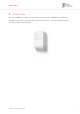
OVERVIEW 1. Overview The Essence MDsense is a battery operated, bi-directional, wireless, multidimensional fall sensor. The MDsense can also be used with either an optional power cable or an optional emergency pull cord, but not both at the same time.
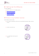
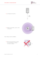
SETTING UP THE MDSENSE 2. Setting Up the MDsense To set up the MDsense: Ensure you have four 1.5 V C alkaline batteries Determine the best location Install and test the MDsense Configure the MDsense 2.1. Determining the Best Location The mounting location should be: 4 In a room up to 4 x 4 m (13.1 x 13.1 ft.) or up to 5 m (16.4 ft.) from the part of the room to be covered.
SETTING UP THE MDSENSE At a height of 2.1 m (6.9 ft.) Within 700 m (2,297 ft.), open air, of the control panel The mounting location should not be: Where objects obscure the coverage area, even partially. For example, bookcases or cabinets.
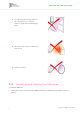
SETTING UP THE MDSENSE A location that has moving objects in the coverage area. For example, curtains or light fixtures with hanging parts. Directly in front of an air conditioner or heat source. In front of a mirror 2.2. Installing and Testing the MDsense To install the MDsense: 1. Identify the location for mounting the MDsense. Refer to 2.1 Determining the Best Location on page 4.
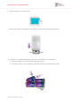
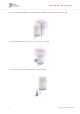
SETTING UP THE MDSENSE 2. Remove the plastic covering the lens. 3. Remove the battery compartment, by pressing the release buttons and pulling downward. 4. Insert four 1.5 V C alkaline batteries into the battery compartment, for each battery: a. Place the negative (-) end of the battery against the spring. b. Press the positive (+) end of the battery toward the battery compartment until it clicks.
SETTING UP THE MDSENSE WARNING! A new battery can cause damage if it is incorrectly installed. 5. On the control panel, press the PAIRING button for five seconds. The control panel beeps and the ring around the EMERGENCY button lights blue. PAIRING button 6. Slide the battery compartment upward into the MDsense until it clicks. The LED flashes. 7. Ensure that the pairing process is successful.
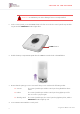
SETTING UP THE MDSENSE a. Press the control panel's PAIRING button twice. The control panel responds, “Control panel entered test mode”. The control panel’s power, communication, and trouble LEDs flash. PAIRING button b. Move close to where you want to install the MDsense. c. Remove the socket cover. The MDsense’s LED lights. The control panel responds with a voice message. d. Replace the socket cover or insert the pull cord or power cable. 9.
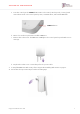
SETTING UP THE MDSENSE 11. Place the back of the MDsense against the wall so that the protective strip touches the wall. 12. Slide the MDsense into the corner. The tape sticks to the wall. 13. Peel off the strip and press the MDsense against the wall.
SETTING UP THE MDSENSE 14. Test detection: a. Walk in front of the MDsense. The LED flashes. b. Lie on the floor. Remain still while the LED is solid red. Remain on the floor until the LED flashes slowly. The control panel announces, “Test successful”. c. Press the control panel’s RESET button. The control panel announces, “control panel exited test mode”. NOTE: After testing is completed during installation, you do not need to test the MDsense again.
OPERATING THE MDSENSE 3. Operating the MDsense The MDsense sends status and event messages to the control panel. 3.1. Notifications The MDsense sends notifications to the control panel when: The MDsense detects a fall The MDsense is removed from its position on the wall or returned to its position The MDsense’s batteries are low or empty The optional pull cord is removed or replaced NOTE: Some types of notifications are sent immediately, while others may take a few minutes. 3.2.
MAINTAINING THE MDSENSE 4. Maintaining the MDsense Maintaining the MDsense includes: Battery replacement Software updates Cleaning the lens 4.1. Replacing the Batteries When the batteries are low, replace the batteries. NOTE: While the batteries are being changed, the MDsense does not function, even when using a power cable. To replace the batteries: 1. Remove the battery compartment, by pressing the release buttons and pulling downward.
MAINTAINING THE MDSENSE 3. Insert four 1.5 V C alkaline batteries into the battery compartment, for each battery: a. Place the negative (-) end of the battery against the spring. b. Press the positive (+) end of the battery toward the battery compartment until it clicks. WARNING! New batteries can cause damage if incorrectly installed. Replace the batteries only with recommended models. Refer to 5. Specifications on page 14. 4. Slide the battery compartment upward into the MDsense until it clicks.
MAINTAINING THE MDSENSE 4.3. Cleaning the Lens To ensure the best performance, clean the lens as necessary. Lens Use a lens cleaning cloth, without any glass cleaning sprays or liquids. Avoid touching the lens with your bare fingers.
SPECIFICATIONS 5. Specifications The following table lists the MDsense’s technical specifications. Category Details Essence Part number ES700MDS Communications Maximum RF range Up to 700 m (2,297 ft.) – open air RF Output 8.3 dBm without RF connector Protocols Proprietary bi-directional radio protocol Modulation and frequency FSK modulation: 869.225 MHz (Europe) 916.5 MHz (North America and Australia) 916.
SPECIFICATIONS Category Details Certifications and approvals CE FCC UL1637 IC EN50130-5 Environment class II EN50134 AS4607 This device complies with FCC Rules Part 15 and with Industry Canada’s license-exempt RSSs. Operation is subject to the following two conditions: (1) This device may not cause harmful interference (2) this device must accept any interference received including interference that may cause undesired operation.
SPECIFICATIONS For Industry Canada: - This Class B digital apparatus complies with Canadian ICES-003. - Cet appareil numerique de la classe B est conforme a la norme NMB-003 du Canada. WARNING! To comply with FCC RF exposure compliance requirements, the device should be located at a distance of at least 20 cm from all persons during normal operation. The antennas used for this product must not be colocated or operated in conjunction with any other antenna or transmitter.
INSTALLING WITH SCREWS Appendix A Installing with Screws To install the mounting base with screws: 1. Prepare the following equipment: A drill with a standard bit 4 x 35 DIN 7982 C screws and wall anchors A Philips head screwdriver 2. Pull the mounting base downward until it stops. 3. Lift the mounting base off the MDsense.
INSTALLING WITH SCREWS 4. Use a screwdriver to clear the screw holes. 5. Ensure that the wall mount is right side up. Top 6. Place and hold the mounting base on the desired location and mark the drilling spots. 7. Drill the holes. 8. Insert wall anchors. 9. Place the mounting base over the wall anchors and screw in the screws.
INSTALLING WITH SCREWS 10. Place the MDsense against the wall mount and pull downward. 11. Continue with step 14 on page 11.
LED INDICATIONS Appendix B LED Indications Following are the MDsense LED indications: LED Display Lights for two seconds Event Power up Pull cord removed/replaced Socket cover removed/replaced Power cord removed/replaced Tamper alarm/restored Blinks quickly for two seconds PIR detection in test mode Remains lit Radar scanning in test mode Blinks slowly for 21 seconds Fall detection Blinks four times Enter test mode 22 Care@Home™ MDsense User Guide
GETTING SUPPORT Appendix C Getting Support Contact your reseller for assistance with your MDsense. The MDsense can be serviced only by the manufacturer.
LEGAL NOTICE Legal Notice Usage of this document, and all information (including product information) provided within, are subject to the following terms and conditions, and all applicable laws. If you do not agree with these terms, please do not access or use the remainder of this document. This document contains highly confidential information, which is proprietary to Essence SmartCare Ltd. and/or its affiliates (hereafter, "Essence").