
Specifications


82 SAM0025A-062397 ESS Technology, Inc.
ES1879 DATA SHEET
REGISTERS
PRELIMINARY
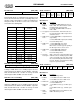
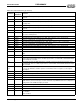
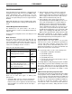
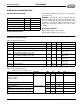
Record Level (B4h, R/W)
Register B4h allows for independent left and right record
levels. Each channel has 16 levels (excluding mute). The
amount of gain or attenuation for each level is different for
microphone than for all other sources. The record levels
are listed in the following table.
DAC Direct Access Holding (B5h, R/W)
Low byte of DAC direct access holding register. Because
the bus between the ISA bus and the FIFO is only 8 bits
wide, the ES1879 needs a location for storage of 16-bit
data. Registers B5h and B6h serve this function.
DAC Direct Access Holding (B6h, R/W)
High byte of DAC direct access holding register. Because
the bus between the ISA bus and the FIFO is only 8 bits
wide, the ES1879 needs a location for storage of 16-bit
data. Registers B5h and B6h serve this function.
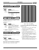
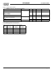
Audio 1 Control 1 (B7h, R/W)
Bit Definitions:
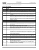
Audio 1 Control 2 (B8h, R/W)
Bit Definitions:
Left channel record level Right channel record level
7 6 5 43210
Record Level Gain for Mic
Gain for Other
Sources
0 +0 dB -6.0 dB
1 +1.5 dB -4.5 dB
2 +3.0 dB -3.0 dB
3 +4.5 dB -1.5 dB
4 +6.0 dB 0 dB
5 +7.5 dB +1.5 dB
6 +9.0 dB +3.0 dB
7 +10.5 dB +4.5 dB
8 +12.0 dB +6.0 dB
9 +13.5 dB +7.5 dB
10 +15.0 dB +9.0 dB
11 +16.5 dB +10.5 dB
12 +18.0 dB +12.0 dB
13 +19.5 dB +13.5 dB
14 +21.0 dB +15.0 dB
15 +22.5 dB +16.5 dB
DAC direct access holding – low byte
7 6 5 43210
DAC direct access holding – high byte
7 6 5 43210
Enable FIFO
to/from
CODEC
Set
oppo-
site bit
3
FIFO
signed
mode
1
FIFO
stereo
mode
FIFO
16-bit
mode
0
Generate
load signal
76543210
Bits Name Description
7 Enable
FIFO to/
from
CODEC
1 = Enable first DMA FIFO connection to
DAC or ADC. This allows transfers to/from
the FIFO and the analog circuitry.
0 = Disable first DMA FIFO connection to
DAC or ADC.
6 Set opposite
bit 3
Reserved function. This bit must be set to
the opposite polarity of bit 3: high for mono
and low for stereo.
5 FIFO signed
mode
1 = First DMA FIFO 2’s complement mode
(signed data).
0 = First DMA FIFO unsigned (offset 8000).
4 – Reserved. Always write 1.
3 FIFO stereo
mode
1 = First DMA FIFO stereo mode.
0 = First DMA FIFO mono mode.
Bit 6 must be set at the opposite polarity of
this bit: high for mono, low for stereo.
2 FIFO 16-bit
mode
1 = First DMA FIFO 16-bit mode.
0 = First DMA FIFO 8-bit mode.
1 – Reserved. Always write 0.
0 Generate
load signal
Write 1. Generates a load signal that copies
DAC Direct Access Holding register to DAC
on the next sample rate clock edge (sample
rate is determined by Extended mode regis-
ter A1h). This bit is cleared after the holding
register is copied to the DAC.
00 0 0
CODEC
mode
DMA
mode
DMA read
enable
DMA transfer
enable
76 5 4 3 2 1 0
Bits Name Description
7:4 – Reserved. Always write 0.
3 CODEC
mode
1 = first DMA converters in ADC mode.
0 = first DMA converters in DAC mode.
2 DMA mode 1 = Auto-Initialize DMA mode.
0 = Normal DMA mode.
1 DMA read
enable
1 = first DMA is read (e.g., for ADC opera-
tion).
0 = first DMA is write (e.g., for DAC opera-
tion).
0DMA
transfer
enable
First DMA active-low reset. When low, first
DMA is allowed to proceed.