
Specifications

ESS Technology, Inc. SAM0025A-062397 79
ES1879 DATA SHEET
REGISTERS
PRELIMINARY
Controller Registers
This is a summary and description of the controller registers. These registers are written to and read from using
commands of the format Axh or Bxh. To enable access to these registers, send the command C6h.
Controller Register Descriptions
Audio 1 Sample Rate Generator (A1h, R/W)
This register should be programmed for the sample rate
for all DAC operations in Extended mode.
The clock source for the sample rate generator is
397.7 kHz if bit 7 is 0 and 795.5 kHz if bit 7 is 1.
The sample rate is determined by the two’s complement
divider in bits 7:0:
Sample_Rate = 397.7 kHz / (128-x) if bit 7 = 0.
= 795.5 kHz / (256-x) if bit 7 = 1.
where x = value in bits 6:0 of register A1h.
Bit Definitions:
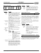
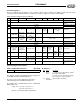
Table 27 ESS Controller Registers Summary
Reg D7 D6 D5 D4 D3 D2 D1 D0 Description
A1h Clock source Sample rate divider
S/W reset, unknown
A2h Filter clock divider
S/W reset, setup for 8 kHz
sampling
A4h Low byte
Audio 1 transfer counter reload
A5h High byte
Audio 1 transfer counter reload
A8h 0 0 0 1
Enable
record
monitor
0
Mono/stereo
select
Analog control
B1h
Game-com-
patible IRQ
Enable IRQ
ovf Ext mode
DMA cntr
Enable IRQ for
FIFO1 HE status
edge
x Audio 1 interrupt
Legacy audio interrupt control
B2h
Game-com-
patible DRQ
Enable DRQ
for Ext mode
DMA
Enable DRQ
game-compatible
DMA
x Audio 1 DRQ
Audio DRQ control
B4h Left Channel Record Level Right Channel Record Level
Record Level
B5h Low byte
DAC direct access holding
B6h High byte
DAC direct access holding
B7h
Enable FIFO
to/from
CODEC
Reserved. Set
opposite
polarity of bit 3
Data type select 1
Stereo/
Mono
mode
select
16-bit/8-bit
mode
select
0
Gener-
ate load
signal
Audio 1 control 1
B8h 0 0 0 0
CODEC
mode
DMA mode
DMA
read/
write
Trans-
fer
enable
Audio 1 control 2
B9h 0 0 0 0 0 0 Transfer type
Audio 1 transfer type
BAh 0
Disable time delay
on analog wake-up
Sign Adjust magnitude
Left channel ADC offset adjust
BBh 0 Sign Adjust magnitude
Right channel ADC offset
adjust
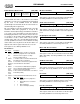
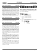
Clock source Sample rate divider
7 6543210
Bits Name Description
7Clock
source
1 = clock source is 795.5 kHz for sample
rates higher than 22 kHz.
0 = clock source is 397.7 kHz for sample
rates lower than or equal to 22 kHz.
6:0 Sample
rate divider
Signed sample rate divider.