
Specifications

72 SAM0025A-062397 ESS Technology, Inc.
ES1879 DATA SHEET
REGISTERS
PRELIMINARY
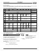
Extended Mode Master Volume Control Registers
This section describes registers related to the master
volume control in Extended mode. These registers are
accessed via I/O addresses Audio_Base+4h and
Audio_Base+5h.
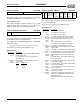
Left Master Volume and Mute (60h, R/W)
This register determines the master volume level for the
left channel.
When in Sound Blaster Pro Compatibility mode, writes to
registers 22h or 32h are translated into writes to 60h and
62h. See “Sound Blaster Pro Master Volume Emulation”
on page 61. Writes to this register when in Compatibility
mode run the risk of being overwritten.
On hardware reset, this register is set to 36h.
Bits Definitions:
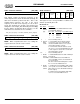
Left Hardware Volume Counter (61h, R/W)
Normally, the hardware volume controls change the
master volume registers 60h and 62h directly, producing
an interrupt at each change. In Split mode, the hardware
volume counters are split from the master volume
counters. Pressing a hardware volume control button
changes the hardware volume counters and produces an
interrupt. The host software can read the counters and
update the master volume registers as needed. Split mode
is enabled by bit 7 of mixer register 64h. If bit 7 is low, this
register is combined with register 60h and cannot be
independently read or written.
Bits Definitions:
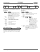
Right Master Volume and Mute (62h, R/W)
This register determines the master volume level for the
right channel.
When in Sound Blaster Pro Compatibility mode, writes to
registers 22h or 32h are translated into writes to 60h and
62h. See “Sound Blaster Pro Master Volume Emulation”
on page 61. Writes to this register when in Compatibility
mode run the risk of being overwritten.
On hardware reset, this register is set to 36h.
Bits Definitions:
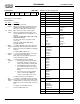
Right Hardware Volume Counter (63h, R/W)
Normally, the hardware volume controls change the
master volume registers 60h and 62h directly, producing
an interrupt at each change. In Split mode, the hardware
volume counters are split from the master volume
counters. Pressing a hardware volume control button
changes the hardware volume counters and produces an
interrupt. The host software can read the counters and
update the master volume registers as needed. Split mode
is enabled by bit 7 of mixer register 64h. If bit 7 is low, this
register is combined with register 62h and cannot be
independently read or written.
Bits Definitions:
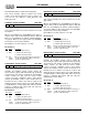
0 Mute Left master volume
76543210
Bits Name Description
7 – Reserved. Always write 0.
6 Mute 1 = Enable left channel mute.
0 = Disable left channel mute.
5:0 Left
master
volume
Bits 5:0 select the attenuation level in steps of
-1.5 dB. The maximum setting of 3Fh corre-
sponds to 0 dB attenuation.
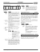
0 Mute Left volume counter
76543210
Bits Name Description
7 – Reserved. Always write 0.
6 Mute 1 = Enable left channel mute.
0 = Disable left channel mute.
5:0 Left
volume
counter
Bits 5:0 select the attenuation level in steps of
-1.5 dB. The maximum setting of 3Fh corre-
sponds to 0 dB attenuation.
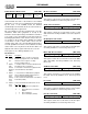
0 Mute Right master volume
76543210
Bits Name Description
7 – Reserved. Always write 0.
6 Mute 1 = Enable right channel mute.
0 = Disable right channel mute.
5:0 Right
master
volume
Bits 5:0 select the attenuation level in steps of
-1.5 dB. The maximum setting of 3Fh corre-
sponds to 0 dB attenuation.
0 Mute Right volume counter
76543210
Bits Name Description
7 – Reserved. Always write 0.
6 Mute 1 = Enable right channel mute.
0 = Disable right channel mute.
5:0 Right
volume
counter
Bits 5:0 select the attenuation level in steps of
-1.5 dB. The maximum setting of 3Fh corre-
sponds to 0 dB attenuation.