
Specifications

ESS Technology, Inc. SAM0025A-062397 71
ES1879 DATA SHEET
REGISTERS
PRELIMINARY
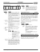
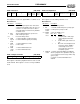
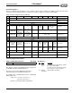
Spatializer Test Control (5Ch, R/W)
In ADC or signal processor test mode, four reads or writes are
needed to access all four bytes. The sequence is controlled
by an internal 2-bit counter. This counter is incremented after
every I/O read or write to mixer register 5Eh. The counter is
reset by an I/O read from mixer register 5Ch.
Reset to zero by hardware reset.
Bit Definitions:
ES978 Mappable Volume Registers 5Dh and 5Fh
This section describes registers related to the ES978
mappable volume registers. These registers are accessed
via I/O addresses Audio_Base+4h and Audio_Base+5h.
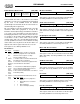
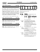
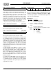
ES978 Mappable Playback Volume (5Dh, R/W)
The mappable volume registers can be assigned to any
single ES978 mixer source. Usually the mixer registers in
the ES978 are slaved to the corresponding register in the
ES1879. Assigning a ES978 mixer register to this register
enables the ES978 mixer source volume to be controlled
independently of the corresponding ES1879 mixer
register. Bits 2:0 of PnP register 2Bh assigns the
mappable volume register to a mixer input of the ES978.
Spatializer Test Data (5Eh, R/W)
Except in ADC test mode, this register returns the current
8-bit gain setting. In ADC test mode, it is used to read back
the ADC values. In signal processor test mode, it is used
to write test pattern data.
In ADC test mode or signal processor test mode, four reads
or writes are needed to access all four bytes in series. The
sequence is controlled by an internal 2-bit counter. This
counter is incremented after every I/O read or write to
mixer register 5Eh. The counter is reset by an I/O read from
mixer register 5Ch.
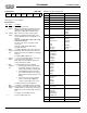
ES978 Mappable Record Volume (5Fh, R/W)
The mappable volume registers can be assigned to any
single ES978 mixer source. Usually the mixer registers in
the ES978 are slaved to the corresponding register in the
ES1879. Assigning an ES978 mixer register to this
register enables the ES978 mixer source volume to be
controlled independently of the corresponding ES1879
mixer register. Bits 2:0 of PnP register 2Bh assigns the
mappable volume register to a mixer input of the ES978.
Left/Right
state flag
Signal
processor
test mode
ADC test
mode
Accelerated
timing
enable
Auto-Limit
test mode
THD
flag
Down
flag
Up
flag
76543210
Bits Name Description
7 Left/
Right
state flag
Read-only. Left/right state flag. This flag indi-
cates which channel the test data is being sam-
pled from.
6 Signal
proces-
sor test
mode
1 = Enable signal processor test mode. This
mode enables the input to the signal processing
logic to be written from the host for test pur-
poses. Poll bit 7 of this register to synchronize.
When it goes high, write to register 5Eh four
times successively to write left low, left high,
right low, right high.
5 ADC test
mode
Poll bit 7 of this register to synchronize, then
read register 5Eh four times successively to
read left low, left high, right low, right high.
4 Acceler-
ated
timing
enable
1 = Accelerated timing.
3 Auto-limit
test
mode
1 = Auto-limit test mode.
2 THD flag THD flag in auto-limit test mode.
1Down
flag
Down flag in auto-limit test mode.
0 Up flag Up flag in auto-limit test mode.
ES978 mappable playback volume left ES978 mappable playback volume right
76543210
DDDDDDDD
76543210
ES978 mappable record volume left ES978 mappable record volume right
76543210