
Specifications

ESS Technology, Inc. SAM0025A-062397 69
ES1879 DATA SHEET
REGISTERS
PRELIMINARY
Serial Mode Filter Divider Control (4Ch, R/W)
This register controls the filter clock rate during serial
mode.
Bits Definitions:
Serial Mode Format/Source/Target Control (4Eh, R/W)
The ES1879 serial port can interface with an external DSP
in several formats and various applications. The format
choices include 8- or 16-bit and mono or stereo. Note that
signed vs. unsigned is controlled by bit 6 of mixer register
48h. The receive and transmit channels can have different
formats, though this is not common.
For receive, there are two choices for the target of the
data:
First channel DMA FIFO
First channel DAC
For the transmit, there are two choices for the source of
the data:
First channel DMA FIFO
First channel ADC
Bits Definitions:
Filter
override
0 2’s complement filter divider
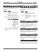
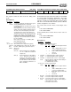
76543210
Bits Name Description
7Filter
override
1 = During serial mode, the filter clock is gener-
ated by dividing down the serial clock.
0 = During serial mode, the filter clock is gener-
ated as follows:
Generally, the filter roll-off should be positioned
at 80% - 90% of the Sample_Rate/2 frequency.
The ratio of the roll-off frequency to the filter
clock frequency is 1:82. In other words, first
determine the desired roll-off frequency by tak-
ing 80% of the Sample_Rate divided by 2, then
multiply by 82 to find the desired Filter Clock
frequency. Use the formula below to determine
the closest divider:
Filter_Clock_Frequency = 7.16 MHz / (256-
Filter_Divider_Register)
6:4 – Reserved. Always write 0.
3:0 2’s com-
plement
filter
divider
These bits are a 2's complement (signed)
value that divides the serial clock. The ratio of
the filter -3 dB frequency to the filter clock is
about 1:41.
Examples:
02h (-14) External Serial Clock 2.048 MHz /
14 / 41 = 3568 Hz for 8000 Hz
sample rate.
0Eh (-2) Internal Serial Clock 1.591 MHz / 2
/ 41 = 19.4 kHz for 44,100 Hz
sample rate. Note that the sample
rate divider is an integer multiple of
the filter divider for 44,100, which
gives maximum performance of
DACs and ADCs.
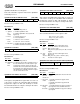
Transmit
source
Transmit
length
Transmit
mode
Receive target
Receive
length
Receive
mode
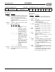
76 5 4 32 1 0
Bits Name Description
7:6 Transmit
source
Transmit register source:
bit 7
bit 6 source
0 0 None: Transmit register held at
zero.
0 1 Audio 1 FIFO (audio 1 in mono
or stereo playback direction).
1 0 Audio 1 ADC (left channel ADC
if mono).
1 1 Reserved.
5Transmit
length
1 = Transmit length is 16 bits, unsigned.
0 = Transmit length is 8 bits, unsigned.
4Transmit
mode
1 = Transmit mode is stereo. Left and right
channels alternate, with left channel data pre-
ceding right channel data.
0 = Transmit mode is mono.
3:2 Receive
target
Receive register target:
bit 3
bit 2 target
0 0 None: Receive register held at
zero.
0 1 Audio 1 FIFO (audio 1 in mono
or stereo record direction).
1 0 Audio 1 DAC (right channel DAC
if mono).
1 1 Reserved.
1 Receive
length
1 = Receive length is 16 bits, unsigned.
0 = Receive length is 8 bits, unsigned.
0 Receive
mode
1 = Receive mode is stereo. Left and right
channels alternate, with left channel data pre-
ceding right channel data.
0 = Receive mode is mono.