
Specifications

ESS Technology, Inc. SAM0025A-062397 55
ES1879 DATA SHEET
PROGRAMMING THE ES1879
PRELIMINARY
9. Set DMA control registers B1h and B2h:
Register B1h: Interrupt Configuration register.
Verify that bit 6 is high. Clear bits 7 and 5.
Register B2h: DRQ Configuration register.
Verify that bit 6 is high. Clear bits 7 and 5.
10.Configure system interrupt controller and DMA
controller.
11. To start DMA:
Set bit 0 of register B8h high. Leave other bits
unchanged.
12.Delay approximately 100 milliseconds to allow analog
circuits to settle.
13.During DMA:
For Auto-Initialize mode DMA transfers, do not send
any commands to the ES1879 at interrupt time, except
for reading Audio_Base+Eh to clear the interrupt
request.
For Normal mode, initialize the system DMA controller
with the address and count of the next block to transfer.
Update the ES1879 Transfer Count registers if the
count is changed. To start the next transfer, clear bit 0
of register B8h, then set it high again.
To stop a DMA transaction in progress, clear bit 0 of
register B8h. To stop a DMA transaction after the
current auto-initialize block is finished, clear bit 2 of
register B8h, wait for the interrupt, and then clear bit 0
of register B8h.
14.After DMA is finished:
Restore the system interrupt controller and DMA
controller to their idle state.
15.To conclude:
Issue another software reset to the ES1879 to initialize
the appropriate registers. This returns the ES1879 to
the DAC direction and turns off the record monitor.
Extended Mode Programmed I/O Operation
The REP OUTSB instruction of the 80x86 family transfers
data from memory to an I/O port specified by the DX
register. The REP INSB instruction is the complementary
function. Use ES1879 port Audio_Base+Fh for block
transfers.
I/O transfers to FIFO are nearly identical to the DMA
process, except that an I/O access to port Audio_Base+Fh
replaces the DMA cycle. Some differences are described
here.
To program in this mode, it is useful to understand how the
FIFO Half-Empty flag generates an interrupt request. An
interrupt request is generated on the rising edge of the
FIFO Half-Empty flag. This flag can be polled by reading
port Audio_Base+Ch. The meaning of this flag depends
on the direction of the transfer:
DAC FIFOHE flag is set high if 0-127 bytes in FIFO
ADC FIFOHE flag is set high if 128-256 bytes in FIFO
Therefore, for DAC operations, an interrupt request is
generated when the number of bytes in the FIFO changes
from >= 128 to < 128. This indicates to the system
processor that 128 bytes can be safely transferred without
over filling the FIFO. Before the first interrupt can be
generated, the FIFO needs to be primed, or filled, with
more than 128 bytes. Keep in mind that data may be taken
out of the FIFO while it is being filled by the system
processor. If that is the case, there may never be >= 128
bytes in the FIFO unless somewhat more than 128 bytes
is transferred. Polling the ES1879 FIFOHE flag to be sure
it goes low in the interrupt handler (or when priming the
FIFO) and perhaps sending a second block of 128 bytes
is a solution to this problem.
For ADC, the interrupt request is generated when the
number of bytes in the FIFO changes from < 128 to >=
128, indicating that the system processor can safely read
128 bytes from the FIFO. Before the first interrupt can be
generated, the FIFO should be emptied (or mostly so) by
reading from Audio_Base+Fh and polling the FIFOHE
flag. It is not safe to use FIFO reset bit 1 of port
Audio_Base+6h indiscriminately to clear the FIFO,
because it may get ADC data out of sync.
As in DMA mode, bit 0 of register B8h enables transfers
between the system and the FIFO inside the ES1879.
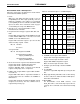
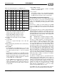
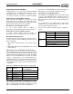
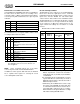
Table 19 Command Sequences for DMA Record
Mono
Stereo
8-bits
16-bits
Unsigned
Signed
Sequence
X X X Reg B7h = 51h
Reg B7h = D0h
X X X Reg B7h = 71h
Reg B7h = F0h
X X X Reg B7h = 51h
Reg B7h = D4h
X X X Reg B7h = 71h
Reg B7h = F4h
X X X Reg B7h = 51h
Reg B7h = 98h
X X X Reg B7h = 71h
Reg B7h = B8h
X X X Reg B7h = 51h
Reg B7h = 9Ch
X X X Reg B7h = 71h
Reg B7h = BCh