
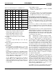
Specifications

54 SAM0025A-062397 ESS Technology, Inc.
ES1879 DATA SHEET
PROGRAMMING THE ES1879
PRELIMINARY
For Normal mode, initialize the system DMA controller
with the address and count of the next block to transfer.
Update the ES1879 Transfer Count registers if the
count is changed. To start the next transfer, clear bit 0
of register B8h, then set it high again.
To stop a DMA transaction in progress, clear bit 0 of
register B8h. To stop a DMA transaction after the
current auto-initialize block is finished, clear bit 2 of
register B8h, wait for the interrupt, and then clear bit 0
of register B8h.
11.After DMA is finished:
Restore the system interrupt controller and DMA
controller to their idle state. Monitor the FIFO Empty
status flag in port Audio_Base+Ch to be sure data
transfer is completed. A delay of 25 milliseconds is
required to let the filter outputs settle to DC levels, then
disable the first DMA DAC input to the mixer with
command D3h.
12.To conclude:
Issue another software reset to the ES1879 to initialize
the appropriate registers.
Extended Mode Audio 1 ADC Operation
Follow the steps below to program the first audio channel
for Extended mode ADC operation:
NOTE:
In Extended mode, there is no Automatic Gain
Control (AGC) performed while recording. If AGC is
necessary, use 16-bit recordings and perform AGC in
system software.
1. Reset:
Write 3h to port Audio_Base+6h instead of 1h as in
Compatibility mode. Bit 1 high specifically clears the
FIFO. The remainder of the software reset is identical
to Compatibility mode. Reset disables the Audio 1 DAC
input to the mixer. This is intended to mask any pops
created during the setup of the DMA transfer.
2. Send command C6h to enable Extended mode
commands.
3. Select the input source:
The ES1879 has seven recording sources. Select the
source using the mixer control register 1Ch.
4. Program input volume register B4h.
5. Program direction and type: registers B8h, A8h, and
B9h:
Register B8h: Set bit 3 high to program the CODEC for
the ADC direction. Set bit 2 low for Normal DMA mode,
high for Auto-Initialize DMA mode.
At this point, the direction of the analog circuits is ADC
rather than DAC. Unless the recording monitor is
enabled, there will be no output from AOUT_L or
AOUT_R until the direction is restored to DAC.
Register A8h: Read this register first to preserve the
bits and modify only bits 3, 1, and 0:
Bits 1:0 10: Mono
01: Stereo
Bit 3 0: Disable Record Monitor for now.
Register B9h:
Bits 1:0 00: Single transfer DMA.
01: Demand transfer:
2 bytes per DMA request.
10: Demand Transfer:
4 bytes per DMA request.
6. Clocks and counters: registers A1h, A2h, A4h, and
A5h:
Register A1h: Audio 1 Sample Rate Generator. Set bit
7 high for sample rates greater than 22 kHz.
Register A2h: Audio 1 Filter Clock Divider.
Registers A4h/A5h: Audio 1 Transfer Count Reload
register (low/high byte, two's complement).
7. Enable Record Monitor if desired:
Register A8h bit 3 = 1: Enable Record Monitor
(optional).
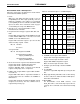
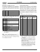
8. Initialize and configure ADC: register B7h. See Table
19.
Register B7h: programs the FIFO (16-bit/8-bit, signed/
unsigned, stereo/mono). The first command sent to
register B7h initializes the DAC and prevents pops.