
Specifications

ESS Technology, Inc. SAM0025A-062397 43
ES1879 DATA SHEET
I/O PORTS
PRELIMINARY
Audio Device
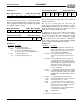
Mixer Address Register (Audio_Base+4h, R/W)
The ES1879 provides a means to read back the Mixer
Address register. Reading back this register is useful for a
“hot-key” application that needs to change the mixer while
preserving the address register.
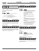
Mixer Data Register (Audio_Base+5h, R/W
)
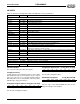
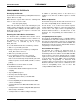
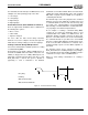
Reset and Status Flags (Audio_Base+6h, W)
Bit Definitions:
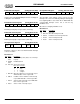
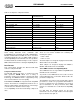
Reset and Status Flags (Audio_Base+6h, R)
Bits 7:4 of port Audio_Base+6h can be used to monitor I/O
activity to the ES1879.
Bits 7:5 are set high after any read from port
Audio_Base+6h. Then specific I/O activity can set these
bits low. When port Audio_Base+6h is read at a later time,
these bits will indicate whether I/O activity has occurred
between the reads from Audio_Base+6h.
In addition, bit 4 can be used to indicate if the DSP or
ES689/ES69x serial interface is in use. Bit 4 is set high if
bit 7 or bit 5 of mixer register 48h is high (software serial
enable or serial reset). It is also set high if the ES689/
ES69x serial interface is active, which is a combination of
bit 4 of mixer register 48h set high and MCLK (ES689/
ES69x serial bit clock) being high periodically.
Bit Definitions:
xA6A5A4A3A2A1 0
76543210
D7 D6 D5 D4 D3 D2 D1 D0
76543210
0
FIFO
reset
SW
reset
76543210
Bits Name Description
7:2 – Reserved. Always write 0.
1 FIFO
reset
1 = Hold ES1879 FIFO in reset.
0 = Release ES1879 FIFO from reset.
Bit 1 has no function for Compatibility mode.
0SW
reset
1 = Hold ES1879 in reset.
0 = Release ES1879 from reset.
Act
flag 2
Act
flag 1
Act
flag 0
Serial
act flag
Digital
power
status
MIDI
mode
FIFO
reset
SW
reset
76543210
Bits Name Description
7 Act flag 2 Set low by I/O reads/writes to MPU-401, Joy-
stick, Configuration devices, as well as PnP I/
O activity (the last includes almost any I/O
write to 279h or A79h if IRPOM = 1).
6 Act flag1 Set low by I/O reads/writes to audio ports
Audio_Base+4h and Audio_Base+5h (mixer
ports).
5 Act flag 0 Set low by I/O writes to audio and FM ports
excepting Audio_Base+4h, Audio_Base+5h,
and Audio_Base+7h. Set low by I/O reads from
audio and FM ports excepting Audio_Base+4h,
Audio_Base+5h, Audio_Base+6h, and
Audio_Base+7h. Also set low by DMA
accesses to ES1879.
4Serial
act flag
1 = Serial activity flag. High if DSP serial mode
is enabled (SE input pin is high or bit 7 of Mixer
Extension register 48h is high) or if an external
ES689/ES69x is using MCLK/MSD to drive the
FM DACs.
3Digital
power
status
1 = ES1879 digital audio is powered-up.
0 = ES1879 digital audio is currently powered
down (power mode 0, 1, and 2).
2 MIDI
mode
1 = The ES1879 is processing a MIDI com-
mand 30h, 31h, 34h, or 35h. In this mode, the
ES1879 is monitoring serial input. Powering-
down may cause a loss of data.
The ES1879 does not automatically wake up
on serial input on the MSI pin.
1 FIFO
reset
FIFO Reset bit.
0 SW reset Software Reset bit.