
Specifications

ESS Technology, Inc. SAM0025A-062397 27
ES1879 DATA SHEET
PERIPHERAL INTERFACING
PRELIMINARY
Split Mode
Normally, the hardware volume controls change the
master volume registers directly and produce an interrupt
at each change. Instead, the ES1879 can be programmed
to use Split mode. In this case, the hardware volume
counters (mixer registers 61h and 63h) are split from the
master volume registers (mixer registers 60h and 62h).
Pressing a hardware volume control button changes the
hardware volume counter and produces an interrupt. The
host software can read the hardware volume counters and
update the master volume registers as needed.
PC Speaker
The PC speaker is supported by a 1-bit DAC with volume
control. The analog output pin PCSPKO is intended to be
externally mixed at the external amplifier, which means
that the PC speaker audio is not transmitted to the ES978
through the expansion audio interface (XA[3:0]) but is
always heard through the portable speakers.
PC Speaker Volume Control
When the PCSPKI signal is high, a resistive path to analog
ground is enabled. The value of the resistor is selected from
among 7 choices to control the amplitude of the output signal.
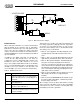
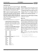
Figure 12 PC Speaker Volume Circuitry
With the external circuit shown in Figure 12, the amplitude
of a square wave output on pin PCSPKO should be
approximately VDDA/2 for maximum volume, i.e., the
internal resistor is approximately 500 ohms (± 30%). The
other levels are relative to this amplitude as follows:
off, -18dB, -15dB, -12dB, -9dB, -6dB, -3dB, +0dB
The purpose of the circuit, beyond volume control of the
speaker, is to prevent digital noise from the PC speaker
signal being mixed into the analog signal. This circuit
provides a clean analog signal. The output can either be
mixed with the AOUT_L and AOUT_R pins externally or
used to drive a simple transistor amplifier to drive an 8
ohm speaker dedicated to producing beeps.
Serial EEPROM Interface
The ES1879 gets Plug and Play configuration data from
an internal masked ROM or an external EEPROM device.
The external EEPROM is accessed by the ES1879 when
IPROM (pin 58) is low. When IPROM is low, the chip select
pin SECS pulses high, enabling access to the external
EEPROM. The external EEPROM device is 512 x 8-bit in
size. When IPROM is high, the ES1879 reads its internal
ROM for PnP configuration data.
The EEPROM interface is shared with the hardware
volume controls. When the EEPROM interface is active,
the volume controls are deactivated. See Figure 13.
The host processor can read or write the EEPROM,
allowing the EEPROM to be reprogrammed or initially
programmed during production testing.
EEPROM ROM FORMAT
'A5' Sync Byte
IRQB IRQA Mapping for IRQB/A
IRQD IRQC Mapping for IRQD/C
IRQE Mapping for IRQE
DRQB DRQA Mapping for DRQB/A
DRQD DRQC Mapping for DRQD/C
PNP Reg 25h Miscellaneous
PNP Reg 26h Miscellaneous
The rest of the data is as per the ISA PnP
specification.
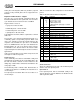
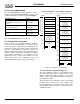
Figure 13 Serial EEPROM – Typical Application
See “Accessing the ROM/EEPROM” on page 30.
PCSPKI
GNDA
PCSPKO
VDDA
470 Ω
.1 µF
.01 µF
ES1879
IPROM
SEDI/VOLUP
SEDO/VOLDN
SECLK/MUTE
SECS
DI
DO
CLK
CS
93LC66
mute
vol down
vol up
(512 x 8-bit serial EEPROM)