
Specifications

24 SAM0025A-062397 ESS Technology, Inc.
ES1879 DATA SHEET
PERIPHERAL INTERFACING
PRELIMINARY
Audio_Base+7h. Only bit 5 (FM reset) and bit 7 (suspend
request) of I/O port Audio_Base+7h are supported in the
ES1879.
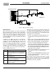
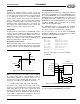
Expansion Audio Interface – Digital
Two wires are used to transmit serial data between the
ES1879 and ES978. The first signal, XSC, acts as a frame
sync and shift clock. The bit clock rate is 3.58 MHz.
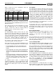
A typical frame consists of:
Sync period – 24 clocks wide
Download period – 144 clocks wide
Turnaround period – 8 clocks wide
Upload period – 80 clocks wide
Total: 256 bit clocks/frame, which is equivalent to a 14 kHz
frame rate.
The function of the upload and download periods is to
continually update corresponding registers within each
device. For example, pressing the VOLUP button in the
expansion unit, transmits the pin state to the ES1879
where it is AND’d with the same pin of the ES1879. The
ES1879 updates its copy of the master volume register.
The ES978 receives the new value in the master volume
register during the first download period of the next frame.
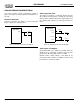
Sync Period
In the sync period, XSC is low for 12 bit clock periods, and
then high for 12 bit clock periods.
Download Period
In the download period, data is transmitted serially from
the ES1879 to the ES978 via the signal XSD. XSC is the
bit shift clock. Data is shifted out of the ES1879 on the
falling edge of XSC. Data is shifted into the ES978 on the
rising edge of XSC.
The download period is 144 bits wide. Each bit takes 4
oscillator clocks (bit rate = 3.58 MHz). The last 8 bits are a
checksum byte.
The upload period is 80 bits wide. The last 8 bits are a
checksum byte.
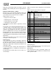
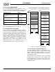
Table 10 contains the data configuration for the download
period.
Turnaround Period
There are 8 bits between the end of the download period
and the start of the upload period.
Upload Period
In the upload period, data is transmitted serially in the
opposite direction, from the ES978 to the ES1879 via the
same signal wire, XSD.
Table 10 Download Period Data Configuration
Byte Bits Function
01:0
4:2
5
6
7
Mode of expansion analog interface
Record source select
Master output enable
1: MIDI loopback test
1: MIDI transmit signal (byte 1 contains
MIDI data)
1 15:8 MIDI transmit data (if bit 7 of byte 0 is high)
2 23:16 XGPO[7:0] data
3 31:24 Playback mixer – Host audio volume
4 39:32 Playback mixer – Line volume
5 47:40 Playback mixer – Mic volume
6 55:48 Playback mixer – Aux A (CD) volume
7 63:56 Playback mixer – Aux B volume
8 71:64 Playback mixer – I
2
S/ES689 volume
9 79:72 Reserved
10 87:80 Record mixer – Line volume
11 95:88 Record mixer – Mic volume
12 103:96 Record mixer – Aux A (CD) volume
13 111:104 Record mixer – Aux B volume
14 119:112 Record mixer – I
2
S/ES689 volume
15 126:120
127
Master volume left
1: Mute left
16 134:128
135
Master volume right
1: Mute right
17 143:136 CRC checksum