
Specifications

22 SAM0025A-062397 ESS Technology, Inc.
ES1879 DATA SHEET
PERIPHERAL INTERFACING
PRELIMINARY
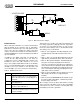
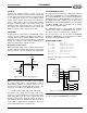
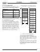
Figure 11 MIDI Serial Interface Adapter
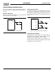
ES978 Interface
When docked, the ES1879 is in constant communication
with the ES978 in the expansion unit. A half-duplex,
bidirectional serial link keeps each chip updated on the
status of the other. For example, the status of the mixer
registers located in the ES1879 are transmitted down to
the ES978. MIDI data received in the ES978 is transmitted
up to the ES1879.
In addition to the digital control link, four analog wires
connect the two chips directly. These four wires are
configured as a pair of differential audio channels. The
ES1879 uses these two audio channels in one of four
ways: stereo playback (ES1879 transmits to the ES978),
stereo record (the ES978 transmits to the ES1879), mono
full-duplex (one mono channel in each direction), and
stereo full-duplex (one stereo channel in each direction).
This interface uses six wires: two analog ground wires and
four analog signal wires (XA[3:0]). The four signal wires
are used in one of five different modes. In each of these
modes, the master always refers to the ES1879 and the
slave always refers to the ES978.
Mode 0 – Stereo playback. Two differential pairs for left
and right channels, transmitted from the master to the
slave.
Mode 1 – Stereo record. Two differential pairs for left and
right channels, transmitted from the slave to the master.
Mode 2 – Monophonic full-duplex. Two differential pairs.
One pair is for monophonic playback from master to
slave, the second pair is for monophonic recording from
slave to master. The mono playback signal is input to both
left and right host audio inputs of the playback mixer. The
mono record signal is derived by averaging the left and
right outputs of the record mixer.
Mode 3 – Stereo full-duplex. The four signals are not used
differentially ( This mode is not supported by the
ES1878).
Mode 4 – Not docked (DOCKED=0). Like Mode 0, except
the analog outputs follow AOUT_L and AOUT_R rather
than the output of the mixer.
After a change of mode, the data is muted at the receiving
end for a period of 25 milliseconds. It is the responsibility
of the master not to have contention caused by both ends
transmitting on the same signal wire.
1
2
3
4
5
6
7
8
9
10
11
12
13
14
15
1
1
2
2
3
4
3
4
5
5
JOYSTICK PORT
DB15P
ISO1
R5
5.6K
R1
10K
R4
2.2K
R2
270
R3
220
C1
220pF
C2
220pF
Q2
2N3904
Q1
2N3904
R6
270
D1
DIN
DIN
J1
J2
MIDI IN
MIDI OUT
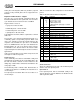
Table 8 ES978 Interface Pins
Pin Description
XA[3:0] Bidirectional differential transmitter/receivers.
Expansion audio bus. These are analog signals
that are DC-coupled to the corresponding pins of
the ES978.
XSD Expansion serial bus data I/O. High-impedance
when DOCKED = 0.
XSC Expansion serial bus clock and frame sync. High-
impedance when DOCKED = 0.
DOCKED Status input that is active-high when the ES1879
is docked to the ES978. This pin has an internal
pull-down to GNDD.