
Specifications

ESS Technology, Inc. SAM0025A-062397 21
ES1879 DATA SHEET
PERIPHERAL INTERFACING
PRELIMINARY
Game/Joystick Interface
The ES1879 includes 8 pins for a dual joystick port. The
digital game port address is decoded for timer pins TA, TB,
TC, and TD, and for switch pins SWA, SWB, SWC, and
SWD. The MIDI serial input and output also come from the
game port connector in most applications.
Four of these eight pins, SW(A-D), are inputs for the
switches of the joysticks. The remaining 4 pins, T(A-D),
are "one-shot" timers that generate pulses of varying
widths, where the width corresponds to the current
resistance of one of the joystick potentiometers.
PC Joysticks
Normally, the host processor is responsible for measuring
the width of the pulse. The ES1879 can also do this
automatically. The host processor can read the measured
widths directly rather than having to do the timing itself.
This is referred to as a “digital joystick.” Bit 1 of Vendor-
Defined Card-Level register 29h determines whether the
joystick port is a digital or analog joystick.
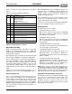
Digital Joysticks
For digital joysticks, the host processor first writes any
value to the joystick port and then reads back seven
separate values (shown in Table 7).
The timer values reported range from 0 to FFFh (0-4095).
The timer clock is 895 kHz.
ES978 Joystick Interface
When docked, a software-programmable bit (bit 0 of
Vendor-Defined Card-Level register 29h) causes the
joystick connected to the ES978 to replace automatically
the one connected to the ES1879f.
Joystick/MIDI External Interface Connector
The joystick portion of the ES1879 reference design is
identical to that on a standard PC game control adapter or
game port. The PC-compatible joystick can be connected
to a 15-pin D-sub connector. It supports all standard PC-
compatible joystick software.
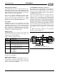
If you need to support two joysticks, a joystick conversion
cable is required. This cable uses a 15-pin D-sub male
connector on one end and two 15-pin D-sub female
connectors on the other end. All signals on this cable have
direct pin-to-pin connection, except for pins 12 and 15. On
the male connector, pins 12 and 15 should be left without
connection. On the female connector, pin 15 is internally
connected to pin 8, and pin 12 is internally connected to
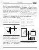
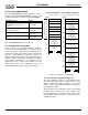
pin 4. The dual joystick port and MIDI port take up only one
slot in your PC, leaving room for other cards. The dual
joystick/MIDI connector configuration is shown in Figure
10.
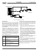
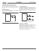
The MIDI serial interface adapter for the joystick/midi
connector is shown in Figure 11.
Figure 10 Dual Joystick/MIDI Connector
Table 7 Digital Joystick Read Values
Read #1 Low byte timer A
Read #2 Low byte timer B
Read #3 Low byte timer C
Read #4 Low byte timer D
Read #5 Bits 3:0 – Upper nibble timer A
Bits 7:4 – Upper nibble timer B
Read #6 Bits 3:0 – Upper nibble timer C
Bits 7:4 – Upper nibble timer D
Read #7 Bit 0 – switch A
Bit 1 – switch B
Bit 2 – switch C
Bit 3 – switch D
+5V
Button
Button
MIDI OUT
MIDI IN
GND
Button
Button
Joystick B Joystick A
X-axis
Y-axis
X-axis
Y-axis
1
2
3
4
5
6
7
8
9
10
11
12
13
14
15