
Specifications

18 SAM0025A-062397 ESS Technology, Inc.
ES1879 DATA SHEET
PERIPHERAL INTERFACING
PRELIMINARY
PERIPHERAL INTERFACING
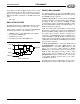
DSP Interface
The ES1879 contains a synchronous serial interface for
connection to a DSP serial interface. The typical
application for this interface is a speakerphone.
DSP Operating Modes
There are two DSP data transfer modes for the ES1879.
The state of a single switch internal to the ES1879
determines which mode is enabled. This switch can route
the first audio channel to the second audio channel DAC.
When the first audio channel is routed to the second audio
channel DAC, Telegaming mode is enabled. Otherwise,
the DSP is operating in its default mode.
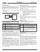
Telegaming Mode
This mode is enabled when two conditions are present:
The DSP serial port must be enabled (i.e., bit 7 of Mixer
register 48h is high).
Bit 0 of mixer register 48h is high. This bit enables
Telegaming mode.
In earlier chips, when the DSP serial port is enabled, the
Audio 1 CODEC is unavailable for use by the first audio
channel. This means digital audio for Sound Blaster Pro-
compatible games is muted. Sound Blaster can use only
the first audio channel for digital audio. The Audio 1
CODEC is used by the DSP.
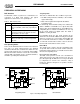
In Telegaming mode, the first audio channel can be
switched over to the Audio 2 DAC. Internally, the first audio
channel is routed to the second audio channel DAC and
the second audio channel has no function. In addition, the
second audio channel mixer volume control is slaved to
the first audio channel mixer volume control.
Default Mode
The default mode operates just like telegaming mode
except that data from the first audio channel cannot be
heard. Data sent through the second audio channel can be
mixed as in Telegaming mode.
No Acoustic Echo Cancellation
The DSP cannot perform acoustic echo cancellation in
either mode. Because the audio from the host does not
pass directly through the DSP, there is no way for the DSP
to compensate for acoustic echo. Therefore, using a
headset for either the microphone or speakers or both is
recommended.
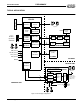
Figure 7 DSP Operating Modes
Table 3 DSP Interface Pins
Pin Description
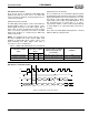
DCLK Data clock input. The rate can vary, but a typical
value is 2.048 MHz (8 kHz x 256). Input with pull-
down.
DX Data transmit. Active output when data is being
transmitted serially from the ES1879; otherwise,
high impedance. Tri-state output.
DR Serial data input with pull-down.
FS Frame sync input for transmit. Software-program-
mable to be active-high or active-low. Input with
pull-down.
ISA
Bus
DMA2
FIFO
DMA1
FIFO
Serializer/
16-bit Stereo
CODEC
Mixer
Microphone
Speaker
DAC
ADC
Deserializer
DSP/CODEC
Port
DAC
ADC
DAC
DAC
16-bit Stereo DAC
FDXO
ISA
Bus
DMA2
FIFO
DMA1
FIFO
Serializer/
16-bit Stereo
CODEC
Mixer
Microphone
Speaker
DAC
ADC
Deserializer
DSP/CODEC
Port
DAC
ADC
DAC
DAC
16-bit Stereo DAC
FDXO
Telegaming Mode Default Mode