
Specifications

14 SAM0025A-062397 ESS Technology, Inc.
ES1879 DATA SHEET
DIGITAL AUDIO
PRELIMINARY
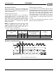
DMA Mode
Extended mode DMA supports both Normal and Auto-
Initialize mode. In addition, Normal mode and Auto-
Initialize mode both support Single and Demand transfer
modes.
Using Single transfer, one byte is transferred per DMA
request. Demand transfer reduces the number of DMA
requests necessary to make a transfer by allowing two or
four bytes to be transferred per DMA request. Thus there
are multiple DMA acknowledges for each DMA request.
For a description of DMA mode including Normal DMA
mode and Auto-Initialize DMA mode see “DMA Mode” on
page 13.
Extended Mode Audio 1 Controller Registers
The following registers control operation of the first audio
channel in Extended mode:
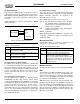
Data Transfers Using the Second Audio Channel
The second audio channel is programmed using mixer
registers 70h through 7Ah. The commands written to the
mixer registers are written to the chip through ports
Audio_Base+4h and Audio_Base+5h.
DMA mode is used when programming the second audio
channel for transfers:
DMA mode:
– Normal (Single or Demand transfer)
– Auto-Initialize (Single or Demand transfer)
In addition, both DMA Normal mode and DMA Auto-
Initialize mode use Single transfer or Demand transfer
modes.
DMA Mode
DMA under the second audio channel supports both
Normal and Auto-Initialize modes. In addition, Normal
mode and Auto-Initialize mode both support Single and
Demand transfer modes.
Using Single transfer, one byte is transferred per DMA
request. Demand transfer reduces the number of DMA
requests necessary to make a transfer by allowing two,
four, or eight bytes to be transferred per DMA request.
Thus there are multiple DMA acknowledges for each DMA
request.
For a description of DMA mode including Normal DMA
mode and Auto-Initialize DMA mode, see “DMA Mode” on
page 13.
Audio 2 Related Mixer Registers
The following registers control DMA operations for the
second audio channel:
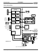
First Audio Channel “CODEC”
The CODEC of the first audio channel is not a true stereo
CODEC in that it cannot perform stereo DAC and ADC
simultaneously. The first audio channel CODEC can be
either a stereo DAC, a stereo ADC, or a mono CODEC.
After reset, the CODEC is set up for DAC operations. Any
ADC command causes a switch to the ADC “direction” and
any subsequent DAC command switches the converter
back to the DAC “direction.”
The DAC output is filtered and input to the mixer. After
reset, input to the mixer from the first audio channel DAC
is muted. This is to prevent pops. The ES1879 maintains
a status flag to determine if the input to the mixer from the
first audio channel DAC is enabled or disabled. The
command D8h returns the status of the flag (00h =
disabled and FFh = enabled). Use command D1h to
enable input to the mixer from the first audio channel DAC
and command D3h to disable the input.
To play a new sound without resetting beforehand when
the status of the analog circuits is not clear, mute the input
to the mixer with command D3h, then set up DAC direction
and level using the direct-to-DAC command:
10h + 80h
Wait 25 msec for the analog circuitry to settle before
enabling the input to the mixer with command D1h.
Address Name
A1h Audio 1 Sample Rate Generator register
A2h Audio 1 Filter Clock Divider register
A4h Audio 1 Transfer Count Reload register – low byte
A5h Audio 1 Transfer Count Reload register – high byte
B1h Audio Interrupt Control register
B2h Audio 1 DRQ Control register
B4h Input Volume Control register
B5h Audio 1 DAC Direct Access register – low byte
B6h Audio 1 DAC Direct Access register – high byte
B7h Audio 1 Control 1 register
B8h Audio 1 Control 2 register
B9h Audio 1 Transfer Type register
Address Name
70h Audio 2 Sample Rate Generator register
72h Audio 2 Filter Clock Divider register
74h Audio 2 Transfer Count Reload register – low byte
76h Audio 2 Transfer Count Reload register – high byte
78h Audio 2 Control 1 register
7Ah Audio 2 Control 2 register