
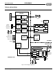
Specifications

ESS Technology, Inc. SAM0025A-062397 13
ES1879 DATA SHEET
DIGITAL AUDIO
PRELIMINARY
Data Transfers in Compatibility Mode
The first audio channel can be programmed using the
standard Sound Blaster-compatible commands. These
commands are written to the chip through port
Audio_Base+Ch.
When programming the first audio channel for
Compatibilty mode transfers one of the following modes
can be used:
Direct Mode
DMA Mode
–Normal
– Auto-Initialize
In addition, both Normal DMA mode and Auto-Initialize
DMA mode can use a special High-Speed mode.
Direct Mode
In Direct mode, the timing for DMA transfers is handled by
the application program. For example, the system timer
can be reprogrammed to generate interrupts at the
desired sample rate. At each system timer interrupt, the
command 10h, 11h, 20h, or 21h is issued, followed by the
sample. Polling of the write buffer available flag
(Audio_Base+Ch [bit 7]) is required before writing the
command and between the command and the data.
NOTE:
The switched capacitor filter is initialized by reset
for an intended sample rate of 8 kHz. In Direct mode, the
application may try to adjust this filter appropriate to the
actual sample rate. The easiest way to do this is to
program the timer with command 40h just as if the
application were using DMA mode.
DMA Mode
In DMA mode, the programmable timer in the ES1879
controls the rate at which samples are sent to the CODEC.
The timer is programmed using command 40h, which also
sets up the programmable filters inside the ES1879. The
ES1879 firmware maintains an internal FIFO (32 levels for
16-bit transfers, 64 levels for 8-bit transfers) that is filled by
DMA transfers and emptied by the timed transfers to the
DAC.
Before a DMA transfer, the application first programs the
DMA controller for the desired transfer size and address,
then programs the ES1879 with the same size
information. At the end of the transfer, the ES1879
generates an interrupt request, indicating that the current
block transfer is complete. The FIFO gives the application
program sufficient time to respond to the interrupt and
initiate the next block transfer.
The ES1879 supports both Normal DMA mode and Auto-
Initialize DMA mode.
Normal DMA Mode
In Normal mode DMA transfers, the DMA controller must
be initialized and the ES1879 must be commanded for
every block that is transferred.
Auto-Initialize DMA Mode
In Auto-Initialize mode, the DMA transfer is continuous, in
a circular buffer, and the ES1879 generates an interrupt
for the transition between buffer halves. In this mode, the
DMA controller and ES1879 need to be set up only once.
High-Speed Mode
The ES1879 supports mono 8-bit DMA transfers at a rate
of up to 44 kHz. Mono 16-bit transfers are supported up to
a rate of 22 kHz.
There is a special High-Speed mode” that allows 8-bit
sampling up to 44 kHz for ADC. This mode uses
commands 98h (Auto-Initialization) and 99h (Normal). No
automatic gain control (AGC) is performed. The input
volume is controlled with command DDh.
Data Transfers in Extended Mode
The first audio channel is programmed using the controller
registers internal to the ES1879. The commands written to
the controller registers are written to the chip through port
Audio_Base+Ch.
When programming the first audio channel for transfers,
one of the following modes can be used:
Programmed I/O
DMA mode:
– Normal (Single or Demand transfer)
– Auto-Initialize (Single or Demand transfer)
In addition, both DMA Normal mode and DMA Auto-
Initialize mode use Single transfer or Demand transfer
mode.
Programmed I/O
For some applications, DMA mode is not suitable or
available for data transfer, and it is not possible to take
exclusive control of the system for DAC and ADC
transfers. In these situations, use I/O block transfers within
an interrupt handler. The REP OUTSB instruction of the
80x86 family transfers data from memory to an I/O port
specified by the DX register. The REP INSB instruction is
the complementary function. Use ES1879 port
Audio_Base+Fh for block transfers.
I/O transfers to FIFO are nearly identical to the DMA
process, except that an I/O access to port
Audio_Base+Fh replaces the DMA cycle. For details
about Programmed I/O, operation see “Extended Mode
Programmed I/O Operation” on page 55.