
Specifications

12 SAM0025A-062397 ESS Technology, Inc.
ES1879 DATA SHEET
ISA BUS INTERFACE
PRELIMINARY
ISA BUS INTERFACE
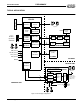
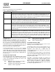
Table 1 shows the pins used to interface the ES1879 with the ISA bus.
DIGITAL AUDIO
The ES1879 incorporates two audio channels:
Audio 1 The first audio channel. This channel is used for
Sound Blaster Pro-compatible DMA, Extended
mode DMA, and Programmed I/O. It can be
used for either record or playback. This channel
can be mapped to any of the three 8-bit ISA
DMA channels: 0, 1, or 3.
Audio 2 The second audio channel. This channel is used
for audio playback in full-duplex mode. This
channel can be mapped to any of the three 8-bit
ISA DMA channels or the 16-bit channel.
The two DMA sources are mapped to the four DMA pin
pairs through PnP registers. Also, the four DMA pin pairs
are assigned ISA DMA channel numbers by Vendor-
Defined Card-Level registers 23h and 24h.
In order for a DRQ output pin to be
driving
(as opposed to
high-impedance
), two things must occur:
1. The PnP register for the DMA of a given device
must match the ISA DMA channel number of the
pin.
2. The given device must be activated (that is, bit 0 of
PnP register 30h must be high).
For detailed information, see “PnP Configuration and
Registers” .
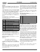
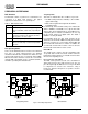
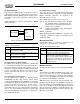
Figure 5 Data Transfer Modes
Pro
g
rammin
g
Data Transfers
Programming Data transfers can be quite complicated
with the ES1879. Both Compatibility mode and Extended
mode offer a variety of modes for conducting transfers.
The commands to enable the different transfers varies
depending on which audio channel is used and which
mode (Compatibility or Extended) is used.
The biggest difference in available data transfer modes is
between audio channel 1 and audio channel 2. This is
illustrated in Figure 5. Audio 2 allows only for DMA mode.
Audio 1 allows for Direct mode and DMA mode when
using Compatibility mode. Audio 1 allows for Programmed
I/O and DMA mode when using Extended mode.
Data Formats
See “Data Formats” on page 48.
Table 1 ES1879 ISA Bus Interface
Pin I/O Description
A[11:0] I ISA address bus.
AEN I ISA address valid when active-low, DMA when high.
D[7:0] I/O ISA data bus. 24 mA drivers.
IOWB O ISA active-low write strobe.
IORB I ISA active-low read strobe.
IRQ(A-E) O/Hi Z ISA interrupt request. 16 mA driver.
DACKB(A-D) I ISA active-low DMA acknowledge.
DRQ(A-D) O/Hi Z ISA active-high DMA request.
RESET I ISA active-high reset.
Digital Audio
Audio 1 Audio 2
Compatibility
Mode
Extended
Mode
Direct
Mode
DMA
Mode
ProgrammedDMA
Mode I/O
DMA
Mode