
Specifications

102 SAM0025A-062397 ESS Technology, Inc.
ES1879 DATA SHEET
APPENDIX C: I
2
S ZV INTERFACE REFERENCE
PRELIMINARY
Audio Interface Timing
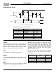
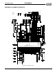
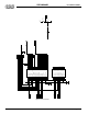
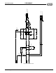
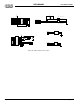
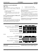
Figure 31 Audio Interface Timing
LRCLK
This signal determines which audio channel (left/right) is
currently being input on the audio serial data input line.
LRCLK is low to indicate the left channel and high to
indicate the right channel. Typical frequency values for this
signal are 48 kHz, 44.1 kHz, 32 kHz, and 22 kHz.
SCLK
This signal is the serial digital audio PCM clock.
SDATA
This signal is the digital PCM signal that carries the audio
information. Digital audio data is transferred using the I
2
S
format.
MCLK
This signal is the master clock for the digital audio. MCLK
is asynchronous to LRCLK, SDATA, and SCLK.
MCLK must be either 256 times or 384 times the desired
Input Word Rate (IWR). IWR is the frequency at which
words for each channel are input to the DAC and is equal
to the LRCLK frequency. The following table illustrates
several standard audio word rates and the required SCLK
and MCLK frequencies. Typically, most devices operate
with 384 x Fs master clock.
The ZV Port audio DAC should support an MCLK
frequency of 384 x Fs. This results in the frequencies
shown below.
LRCLK
SCLK
SDATA
t
slrs
t
SCLKl
t
sdlrs
t
sdh
t
SCLKh
t
slrd
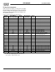
Table 34 AC Parameters for Audio Signals
Symbol Parameter Min
t
slrd
LRCLK delay 2ns
t
slrs
LRCLK setup 32ns
t
SCLKl
bit clock low 22ns
t
SCLKh
bit clock high 22ns
t
sdlrs
data setup 32ns
t
sdh
data hold 2ns
LRCLK (kHz)
Sample Frequency
SCLK (MHz)
32 x Fs
MCLK (MHz)
384 x Fs
22 0.704 8.448
32 1.0240 12.2880
44.1 1.4112 16.9344
48 1.5360 18.4320