
Specifications

100 SAM0025A-062397 ESS Technology, Inc.
ES1879 DATA SHEET
APPENDIX C: I
2
S ZV INTERFACE REFERENCE
PRELIMINARY
APPENDIX C: I
2
S ZV INTERFACE REFERENCE
(Excerpted from “PCMCIA Document Number 0135 – Release 010 1/15/96”)
Overview
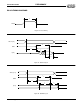
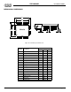
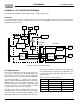
The following diagram shows the system-level concept of the ZV port. The diagram demonstrates how TV in a window
could be achieved in a portable computer with a low-cost PC card. An MPEG or teleconferencing card could also be
plugged into the PC Card slot.
Figure 29 Example ZV Port Implementation
The Audio Interface
The ZV Port compliant PC card sends audio data to the
host computer using Pulse Code Modulation (PCM). The
audio data is transferred using the serial I
2
S format. The
audio circuitry in the host system is primarily a PCM DAC.
The PCM audio DAC is a complete stereo digital-to-
analog system including digital-interpolation, delta-sigma
digital-to-analog conversion, digital de-emphasis, and
analog filtering. Only the normal power supply decoupling
components and one resistor and capacitor per channel
for analog signal reconstruction are required.
The DAC accepts data at standard audio frequencies
including 48 kHz, 44.1 kHz, 32 kHz, and 22 kHz. Audio
data is input via the serial data input pin, SDATA. The Left/
Right Clock (LRCLK) defines the channel and delineation
of data. There Serial Clock (SCLK) clocks the audio data
into the input data buffer. The master clock (MCLK) is used
to operate the digital interpolation filter and the delta-
sigma modulator.
PCI LOCAL BUS
256K x 16
DRAM
VGA
PC CARD
HOST
ADAPTER
ANALOG
ENCODER
AUDIO
CODEC
AMP
TV
LCD
CRT
SPEAKERS
PC CARD
INTERFACE
PCM
CONVERTER
VIDEO
DECODER
19
19
4
4
MOTHERBOARD
PCM
AUDIO
INPUT
ZV PORT
(VIDEO)
PC CARD
SLOT
PC CARD
AUDIO
VIDEO & CONTROL
AUDIO
VIDEO
NTSC/PAL
RF SIGNAL
INPUT
INPUT
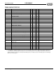
Table 33 Common Clock Frequencies
MCLK (MHz)
LRCLK (KHz) 256x 384x
22 5.632 8.448
32 8.192 12.2880
44.1 11.2896 16.9344
48 12.2880 18.4320