
Specifications

92 SAM0023-122898 ESS Technology, Inc.
ES1869 DATA SHEET
APPENDIX B: ES689/ES69X DIGITAL SERIAL INTERFACE
APPENDIX B: ES689/ES69x DIGITAL SERIAL INTERFACE
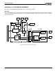
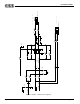
In order for the ES689/ES69x to acquire the FM DAC, bit
4 of mixer register 48h inside the ES1869 must be set
high. When bit 4 is set high, activity on the MCLK signal
causes the ES1869 to connect the FM DAC to the ES689/
ES69x. If MCLK stays low for more than a few sample
periods, the ES1869 reconnects the FM DAC to the FM
synthesizer.
After reset, the ES689/ES69x transmits samples
continuously. In this mode, bit 4 of mixer register 48h must
be set/cleared to assign the current owner of the FM DAC.
The ES689/ES69x can be programmed to enter Activity-
Detect mode using system exclusive command 4. For
more information on system exclusive commands, see the
appropriate ES689/ES69x Data Sheet. In this mode, the
ES689/ES69x blocks the serial port output (i.e., sets MSD
and MCLK low) if no MIDI input is detected on the MSI pin
for a period of 5 seconds. It resumes output of data on the
serial port as soon as a MIDI input is detected on the MSI
pin. This is the recommended mode of operation.
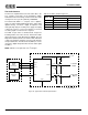
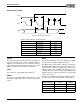
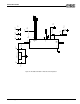
Bit Clock Rate (MCLK): 2.75 MHz
Sample Rate: 42,968.75 Hz
MCLK Clocks per Sample: 33 clocks (+ 31 missing clocks)
MSD Format: 16 bits, unsigned (offset 8000h), MSB first
MSD changes after rising edge of MCLK. Hold time relative to MCLK rising edge is 0-25 nanoseconds.
00 01 02 14 15 16 17 29 30 31 32 33 62 63 00
L15 L14 L13 L1 L0 R15 R14 R2 R1 R0
MSD
MCLK
MSB MSB
Right DataLeft Data