
Specifications

ESS Technology, Inc. SAM0023-122898 75
ES1869 DATA SHEET
POWER MANAGEMENT
Partial Power-Down
When the ES1869 is in the partial power-down state, the
power supply remains connected to the chip during power-
down and the chip’s analog section remains active while
the digital circuits are mostly inactive.
The total current used by the ES1869 can be reduced by
a factor of two or more by putting the ES1869 in a partial
power-down state. The crystal oscillator, if used, continues
to operate. The analog circuitry remains powered up so
that AUXA_L, AUXA_R, AUXB_L, AUXB_R, LINE_L,
LINE_R, and MIC audio sources can continue to be heard.
FM and DAC audio are automatically muted. No pops
should occur when returning from partial power-down to
full power-up state.
The following items are active during partial power-down
operation:
• Oscillator is enabled.
• MPU-401 operates.
• PnP operates.
• Configuration device operates.
• H/W volume operates.
• Mixer operates.
• Analog operates.
• Joystick operates.
• Audio device is disabled, FM disabled.
• Automatic wake-up with any I/O activity to FM or audio
registers except Audio_Base+4h, Audio_Base+5h,
Audio_Base+6h, Audio_Base+7h.
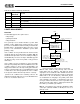
Causing Partial Power-Down
To enter partial power-down mode, bit 3 of port
Audio_Base+7h must be high and must remain high while
pulsing bit 2 high, then low.
Example:
Powering down the ES1869 using system software timer
interrupt:
In this example, it is assumed that the ES1869 is not using
a crystal for its clock.
From a timer interrupt routine, read Audio_Base+6h to
monitor activity. After one minute of I/O inactivity, you
decide that you want the ES1869 to power down
completely, then return from a timer interrupt. The ES1869
wakes up automatically upon any I/O access to the
ES1869 by any application.
1. See if the ES1869 is already powered down (bit 3 of
port Audio_Base+6h = 0). If so, there is nothing to do.
2. Check if the ES1869 is being held in reset by reading
bit 0 of port Audio_Base+6h. If bit 0 is high, the reset
must be released before power-down can occur: Clear
bit 0 of port Audio_Base+6h, then delay 1 millisecond
or more for the ES1869 processor to complete its
initialization.
3. Check to see if the ES1869 is in MIDI serial interface
mode by testing bit 2 of port address Audio_Base+6h.
If so, it may not be prudent to power-down. While the
ES1869 can power-down when in MIDI mode, it does
not automatically wake up if serial data comes in to the
MSI pin, and such data will be lost.
4. Send a power-down request to the chip by clearing bit
3 in port Audio_Base+7h, then pulsing bit 2 high, then
low. The other bits of this register should be preserved.
The ES1869 processor sees the rising edge of bit 2 of
port Audio_Base+7h as an interrupt request to power-
down.
Waking from Partial Power-Down
Any I/O activity, except Audio_Base+6h or
Audio_Base+7h, automatically wakes the ES1869 from a
partial power-down.
A low input on any of the three hardware volume control
pins (VOLUP, VOLDN, or MUTE) also acts as a wake-up
event.
Full Power-Down
Complete power-down reduces the operating current to
less than 50 microamps.
The following items are indicators of full power-down
operation:
• Nothing operates, except for some programmed I/O.
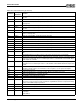
• The activity flags from a port Audio_Base+6h read are:
0 Full power-down. Crystal oscillator
disabled. AOUT_L and AOUT_R held at
approximately CMR by high value
resistors.
All inputs
static at
VDDD or
GND.
1 Partial power-down. Joystick, MPU-401
are up. Audio, FM, ES689/ES69x interface,
and DSP serial interface are down.
Digital
standby.
2 Full power-up. This is the state after
hardware reset.
Normal
operating
conditions.
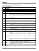
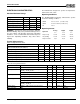
Bits Name Description
7 Act flag 2 Activity latch PnP, Joystick, MPU-401, Configu-
ration, CD-ROM, Modem, or GPI/O or DMA
activity.
6 Act flag 1 Activity latch: Audio_Base+4h,
Audio_Base+5h I/O.
5 Act flag 0 Activity latch: Audio (except Audio_Base+4h,
Audio_Base+5h, Audio_Base+6h read,
Audio_Base+7h read/write), FM I/O or DMA.
4 Serial act DSP and ES689/ES69x serial activity status.