
Specifications

74 SAM0023-122898 ESS Technology, Inc.
ES1869 DATA SHEET
POWER MANAGEMENT
POWER MANAGEMENT
Overview
The ES1869 supports three power states:
• full power-up
• partial power-down
• full power-down
The system processor decides whether to power down
partially or fully. Activity flags monitored by the system
processor are available to track I/O activity to and from the
ES1869. After a predetermined idle period, the system
processor can command the ES1869 to power down
partially or fully.
If the oscillator clock is provided from an external circuit,
automatic wake-up upon I/O activity is available. With the
automatic wake-up feature, the act of reading or writing to
an ES1869 I/O port causes the chip to immediately power
up without losing context from partial or fully powered-
down states.
If the oscillator clock is provided by a crystal, automatic
wake-up from partial power-down is available because the
oscillator continues to run as long as the ES1869 is not
fully powered down. Once the chip is fully powered down,
however, automatic wake-up is not available with a crystal
oscillator due to the start-up requirements of the oscillator
itself. System software must then provide for a start-up
period for the oscillator before returning control to the
application programs that may access the ES1869. There
is no loss of context in either case.
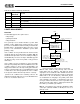
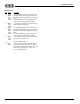
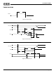
Figure 22 Summary of Power States in the ES1869
Note 1: After return to full power-up state from full
power-down state, the AOUT_L and AOUT_R analog
output pins are not enabled for 48 to 64 milliseconds. The
chip should remain in the full power-up state for at least 64
milliseconds to be sure the AOUT_L and AOUT_R pins
are enabled before changing to the partial power-down
state. Otherwise the AOUT_L and AOUT_R pins may
never get enabled. For this reason it is not possible to go
directly from full power-down to partial power-down and
have AOUT_L and AOUT_R enabled.
Note 2: A low input on any of the three hardware volume
control pins (VOLUP, VOLDN, or MUTE) also acts as a
wake-up event.
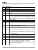
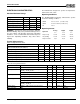
DCh 1 read Return current input gain, 0-15, (valid during 16-bit ADC and 8-bit “high speed mode” ADC).
DDh 1 write Write current input gain, 0-15, (valid during 16-bit ADC and 8-bit “high speed mode” ADC).
E1h 2 reads Return version number high (3), followed by version number low (1). This indicates Sound Blaster
Pro compatibility.
F2h Generate an interrupt for test purposes.
FDh Forces power-down. Software or hardware reset. Required for wake-up.
Table 26 Command Summary (Continued)
Command
Data Byte(s)
Write/Read
Function
Mode Description Notes
full power-up
partial power-up/
analog stays on
oscillator/clock
continues to run
full power-down
AOUT disabled
oscillator stopped
delay > 25ms
Reset
Set bit 3 of Audio_Base+7h
Pulse bit 2 of Audio_Base+7h
Any I/O except
Audio_Base+6h
Clear bit 3 of Audio_Base+7h
If crystal, set bit 3 of
Audio_Base+7h to enable
the oscillator and to enter
partial power-up state after a delay
running, set bit 3 of
Audio_Base+7h to
If external clock
Note 2
Note 1
or Audio_Base+7h
enter partial power-up state
Clear bit 3 of Audio_Base+7h
power-down