
Specifications

ESS Technology, Inc. SAM0023-122898 69
ES1869 DATA SHEET
REGISTERS
DRQ Control (B2h, R/W)
Bit Definitions:
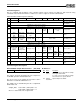
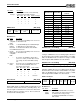
Record Level (B4h, R/W)
Register B4h allows for independent left and right record
level. Each channel has 16 levels (excluding mute). The
amount of gain or attenuation for each level is different for
microphone than for all other sources. The record levels
are listed in the following table.
DAC Direct Access Holding (B5h, R/W)
Low byte of DAC direct access holding register. Because
the bus between the ISA bus and the FIFO is only 8 bits
wide, the ES1869 needs a location for storage of 16-bit
data. Registers B5h and B6h serve this function.
DAC Direct Access Holding (B6h, R/W)
High byte of DAC direct access holding register. Because
the bus between the ISA bus and the FIFO is only 8 bits
wide, the ES1869 needs a location for storage of 16-bit
data. Register B5h and B6h serve this function.
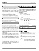
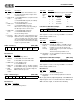
Audio 1 Control 1 (B7h, R/W)
Bit Definitions:
3:0 Audio 1
interrupt
Read-only. Decode the selected interrupt
number for the first audio interrupt.
Game
compatible
DRQ
Enable DRQ for
Extended mode
DMA
Enable DRQ
game compatible
DMA
x Audio 1 DRQ
7 6 5 4 3 2 1 0
Bits Name Description
7 Game
compatible
DRQ
Reserved for Compatibility mode. Leave zero
for Extended mode.
6 Enable
DRQ for
Extended
mode DMA
1 = Enable DRQ outputs and DACKB inputs
for DMA transfers in Extended mode.
0 = Enable block I/O to/from the FIFO in
Extended mode.
5 Enable
DRQ game
compatible
DMA
Reserved for Compatibility mode. Leave zero
for Extended mode.
4 – No function. The DRQ lines always drive
(there is no enable). If neither bit 5 nor bit 6
are set high, the first audio DRQ is always
low.
3:0 Audio 1
DRQ
Read-only. The selected DMA channel num-
ber for the first audio DMA channel are
decoded to set these bits.
Right channel record level Left channel record level
7 6 5 4 3 2 1 0
Bits Name Description
Bit 3 Bit 2 Bit 1 Bit 0 Audio 1 Interrupt
0 0 0 0 2, 9, all others
0 1 0 1 5
1 0 1 0 7
1 1 1 1 10
Bit 3 Bit 2 Bit 1 Bit 0 Audio 1 DRQ
0 1 0 1 0
1 0 1 0 1
1 1 1 1 3
0 0 0 0 all others
Record Level Gain for Mic
Gain for Other
Sources
0 +0 dB -6.0 dB
1 +1.5 dB -4.5 dB
2 +3.0 dB -3.0 dB
3 +4.5 dB -1.5 dB
4 +6.0 dB 0 dB
5 +7.5 dB +1.5 dB
6 +9.0 dB +3.0 dB
7 +10.5 dB +4.5 dB
8 +12.0 dB +6.0 dB
9 +13.5 dB +7.5 dB
10 +15.0 dB +9.0 dB
11 +16.5 dB +10.5 dB
12 +18.0 dB +12.0 dB
13 +19.5 dB +13.5 dB
14 +21.0 dB +15.0 dB
15 +22.5 dB +16.5 dB
DAC direct access holding – low byte
7 6 5 4 3 2 1 0
DAC direct access holding – high byte
7 6 5 4 3 2 1 0
Enable FIFO
to/from
CODEC
Set
oppo-
site bit
3
FIFO
signed
mode
1
FIFO
stereo
mode
FIFO
16-bit
mode
0
Generate
load signal
7 6 5 4 3 2 1 0
Bits Name Description
7 Enable FIFO
to/from
CODEC
1 = Enable first DMA FIFO connection to
DAC or ADC. This allows transfers to/from
the FIFO and the analog circuitry.
0 = Disable first DMA FIFO connection to
DAC or ADC.