
Specifications

68 SAM0023-122898 ESS Technology, Inc.
ES1869 DATA SHEET
REGISTERS
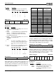
Filter Divider (A2h, R/W)
This register controls the low-pass frequency of the
switch-capacitor filters inside the ES1869. Generally, the
filter roll-off should be positioned at 80% - 90% of the
Sample_Rate/2 frequency. The ratio of the roll-off
frequency to the filter clock frequency is 1:82. In other
words, first determine the desired roll-off frequency by
taking 80% of the Sample_Rate divided by 2, then multiply
by 82 to find the desired filter clock frequency. Use the
formula below to determine the closest divider:
Filter_Clock_Frequency = 7.16 MHz / (256-Filter_Divider_Register)
DMA Transfer Count Reload (A4h, R/W)
On reset, this register assumes the value of 00h.
DMA Transfer Count Reload (A5h, R/W)
On reset, this register assumes the value of F8h.
The FIFO control logic of the ES1869 has a 16-bit counter
for controlling transfers to and from the FIFO. These
registers are the reload value for that counter which is the
value that gets copied into the counter after each overflow
(plus at the beginning of the initial DMA transfer). The
counter is incremented after each successful byte is
transferred by DMA. Since the counter counts up towards
FFFFh and then overflows, the reload value is in two’s
complement form.
For Auto-Initialize mode DMA, the counter is used to
generate interrupt requests to the system processor. In
this mode, the ES1869 allows continuous DMA. In a
typical application the counter is programmed to be one-
half of the DMA buffer maintained by the system
processor. In this application an interrupt is generated
whenever DMA switches from one half of the circular
buffer to the other.
For Normal mode DMA, DMA requests are halted at the
time that the counter overflows, until a new DMA transfer
is commanded by the system processor. Again, an
interrupt request is generated to the system processor if
bit 6 of register B1h is set high.
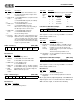
Analog Control (A8h, R/W)
When programming the FIFO for DMA playback modify
only bits 1:0. When programming the FIFO for DMA record
modify only bits 3, 1, and 0. Read this register first to
preserve the remaining bits.
Bit Definitions:
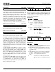
Legacy Audio Interrupt Control (B1h, R/W)
Bit Definitions:
Filter clock divider
7 6 5 4 3 2 1 0
DMA transfer count reload – low byte
7 6 5 4 3 2 1 0
DMA transfer count reload – high byte
7 6 5 4 3 2 1 0
0 0 0 1
Record monitor
enable
0
Stereo/mono
select
7 6 5 4 3 2 1 0
Bits Name Description
7:5 0 Reserved. Always write 0.
4 1 Reserved. Always write 1.
3 Record
monitor
enable
1 = Enable record monitor.
0 = Disable record monitor.
2 0 Reserved. Always write 0.
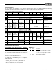
1:0 Stereo/
mono
select
Select operation mode of first DMA converters.
Game
compatible
IRQ
Enable IRQ ovf Ext
mode DMA cntr
Enable IRQ for
FIFO1 HE status
edge
x Audio 1 interrupt
7 6 5 4 3 2 1 0
Bits Name Description
7 Game com-
patible IRQ
Reserved for Compatibility mode. Leave zero
for Extended mode.
6 Enable IRQ
ovf Ext
mode DMA
cntr
Set high to receive interrupts for each over-
flow of the ES1869 DMA counter in Extended
mode.
5 Enable IRQ
for FIFO1
HE status
edge
Set high to receive interrupts for FIFO Half-
Empty transitions when doing block I/O to/
from the FIFO in Extended mode.
4 – No function. The audio device activate bit
serves the purpose of enabling the interrupt
pin.
Bit 1 Bit 0 Mode
0 0 Reserved
0 1 Stereo
1 0 Mono
1 1 Reserved