
Specifications

ESS Technology, Inc. SAM0023-122898 65
ES1869 DATA SHEET
REGISTERS
Bit Definitions:
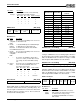
Audio 2 Control 2 (7Ah, R/W)
This register is reset to zero by hardware or software
reset.
Bit Definitions:
Audio 2 DAC Mixer Volume (7Ch, R/W)
This register is reset to zero by hardware reset.
Mic Preamp, MONO_IN and MONO_OUT (7Dh, R/W)
This register is reset to 08h by hardware reset.
Bit Definitions:
I
2
S Interface (7Fh, R/W)
Bit Definitions:
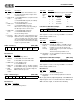
Bits Name Description
7:6 Single/
demand
transfer
Single/deman transfer.
5 0 Reserved. Always write 0.
4 Auto-
initialize
1 = Auto-initialize mode. After the transfer counter
rolls over to 0, it is automatically reloaded and
DMA continues. The second channel interrupt
flag will be set high.
0 = Normal mode. After the transfer counter rolls
over to 0, it is reloaded but DMA stops. Bit 1 of
this register is cleared. The 2nd channel interrupt
flag will be set high.
3:2 0 Reserved. Always write 0.
1 Enable
2nd
chan
DMA
1 = 2nd channel DMA enabled for data to be writ-
ten into the 2nd channel FIFO (32 words deep).
0 = Second channel DMA not enabled.
This bit is cleared when the transfer counter rolls
over to zero, if not in Auto-initialize mode.
0 Enable
FIFO to
2nd
chan
DAC
1 = Data transfer from the FIFO to the 2nd chan-
nel DAC is enabled (or, in special cases, from the
FIFO to the DSP serial port or to be digitally
mixed with the FM synthesizer output).
0 = Data transfer not enabled.
2nd chan IRQ IRQ mask 0 0 0 Signed
stereo/
mono
16-bit/
8-bit
7 6 5 4 3 2 1 0
Bits Name Description
7 2nd
chan-
nel IRQ
This latch is set high when the DMA counter rolls
over to zero, or when a 1 is written to this bit. The
latch is cleared by writing a zero to this bit, or by
hardware or software reset.
6 IRQ
mask
This bit is AND'ed with bit 7 to produce the sec-
ond DMA channel interrupt request.
5:3 0 Reserved. Always write 0.
2 Signed 1 = Data is in signed, two's complement format.
0 = Unsigned data.
1 Stereo/
mono
1 = Stereo data. This format is reserved for Inter-
leave mode when using the DSP serial interface.
0 = Mono data.
0 16-bit/
8-bit
1 = 16-bit samples.
0 = 8-bit samples.
Bit 7 Bit 6 Function
0 0 Single: 1 DACK per DRQ
0 1 Demand: 2 DACKs per DRQ
1 0 Demand: 4 DACKs per DRQ
1 1 Demand: 8 DACKs per DRQ
Left channel volume Right channel volume
7 6 5 4 3 2 1 0
0 0 0 0
Enable
+26 dB mic
amp
MONO_OUT
source select
Enable
MONO_IN mix
with AOUT_L/R
7 6 5 4 3 2 1 0
Bits Name Description
7:4 0 Reserved. Always write 0.
3 Enable +26
dB mic amp
1 = Enable +26 dB microphone preamp gain.
0 = Mic preamp is 0 dB.
2:1 MONO_OUT
source select
Mono_Out source select.
0 Enable
MONO_IN
mix with
AOUT_L/R
1 = MONO_IN is mixed with AOUT_L and
AOUT_R after playback mixer, 3-D effect,
and master volume stages. Mix is unity gain.
Reserved
Music digital
record
I
2
S data
activity
I
2
S clock
activity
MODE
pin
Enable I
2
S connect
to music DAC
7 6 5 4 3 2 1 0
Bits Name Description
7:5 – Reserved.
4 Music
digital
record
1 = Enable direct digital recording of Music DAC
data (including FM, ES689/ES69x, or I
2
S). In
this mode, the first DMA channel must be
enabled for stereo recording. The sample rate
is determined by the music DAC sample rate
rather than by controller register A1h.
3 I
2
S data
activity
This bit is set high if IISDATA has been high at
least once since it was last cleared by software.
Bit 2 Bit 1 Mono_Out Source
0 0 Mute (CMR)
0 1 CIN_R pin (1st channel DAC,
R channel playback, after fil-
ter stage)
1 0 2nd channel DAC, R channel
output
1 1 Mono mix of L and R record
level stage outputs. Con-
trolled by record source select
and record level registers