
Specifications

64 SAM0023-122898 ESS Technology, Inc.
ES1869 DATA SHEET
REGISTERS
Line Record Volume (6Eh, R/W)
This register controls the record volume for the line input.
Set low by hardware reset but not by mixer reset.
Mono_In Record Volume (6Fh, R/W)
This register controls the record volume for the mono
input. Set low by hardware reset but not by mixer reset.
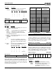
Audio 2 Sample Rate (70h, R/W)
Program this register for the sample rate for Audio 2 DAC
operations in extended mode.
The sample rate is determined by the two’s complement
divider in bits 6:0.
Sample_Rate = Clock_Source / (128 - Sample_Rate_Divider)
This register is reset to zero by hardware reset.
Bit Definitions:
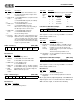
Audio 2 Mode (71h, R/W)
This register is reset to zero by hardware reset.
Bit Definitions:
Audio 2 Filter Clock Rate (72h, R/W)
In Asynchronous mode, this register determines the filter
clock rate of the second channel switched capacitor filter.
If used, this register is programmed in the same manner
as controller register A2h.
This register is reset to zero by hardware reset.
Audio 2 Transfer Count Reload (74h, R/W)
Audio 2 Transfer Count Reload (76h, R/W)
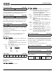
Audio 2 Control 1 (78h, R/W)
Left Line record Right Line record
7 6 5 4 3 2 1 0
Left Mono_In record Right Mono_In record
7 6 5 4 3 2 1 0
Master clock Two’s complement rate divider
7 6 5 4 3 2 1 0
Bits Name Description
7 Master
clock
Selects the master clock for the sample rate gen-
erator:
1 = 768 kHz (used to generate 48 kHz, 32 kHz, 16
kHz, 8 kHz, and so on).
0 = 793.8 kHz (used to generate 44.1 kHz, 22.05
kHz, and so on).
6:0 Two’s
comp
rate
divider
Two’s complement divisor of master clock to pro-
duce sample rate. Examples:
0 0
New reg
A1h
4x
mode
SCF2
bypass
SCF1
bypass
Async
mode
FM mix
7 6 5 4 3 2 1 0
Bits Name Description
7:6 0 Reserved. Always write 0.
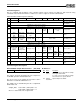
Rate Register 70h
8000 A0h
48000 F0h
44100 6Eh
5 New
reg A1h
1 = Register A1h behaves in the same manner as
mixer register 70h, which gives more accurate
sample rates that are divisors of 48 kHz.
0 = Enables register A1h to behave exactly as in
previous ESS AudioDrive
®
chips.
4 4x
mode
1 = 2nd channel DAC is in 4x oversampling mode.
0 = 2nd channel DAC is not oversampling.
3 SCF2
bypass
1 = 2nd channel DAC switched capacitor filter is
bypassed.
0 = 2nd channel DAC SCF is not bypassed.
NOTE: the SCF is always bypassed in 4x
oversampling mode.
2 SCF1
bypass
1 = 1st channel CODEC switched capacitor filter
is bypassed.
0 = 1st channel CODEC SCF is not bypassed.
1 Async
mode
1 = 2nd channel DAC is asynchronous to the
sample rate of the 1st channel.
0 = 2nd channel DAC is slaved to the sample rate
and filter rate of the 1st channel.
0 FM mix 1 = 2nd channel DMA is slaved to the FM synthe-
sizer sample rate and the DMA data is digitally
mixed to the FM synthesizer output.
Two’s complement filter rate divider
7 6 5 4 3 2 1 0
Two’s complement transfer count – low byte
7 6 5 4 3 2 1 0
Two’s complement transfer count – high byte
7 6 5 4 3 2 1 0
Single/demand
transfer
0 Auto-initialize 0 0
Enable 2nd
chan DMA
Enable
FIFO to 2nd
chan DAC
7 6 5 4 3 2 1 0
Bits Name Description