
Specifications

62 SAM0023-122898 ESS Technology, Inc.
ES1869 DATA SHEET
REGISTERS
3-D Enable (50h, R/W)
3-D effect uses Spatializer
®
VBX™ technology, provided by
Desper Products, Inc., a subsidiary of Spatializer Audio
Laboratories, Inc.
Bit Definitions:
3-D Level (52h, R/W)
3-D effect uses Spatializer
®
VBX™ technology, provided by
Desper Products, Inc., a subsidiary of Spatializer Audio
Laboratories, Inc.
Reset to zero by hardware reset.
Bit Definitions:
Left Master Volume and Mute (60h, R/W)
Right Master Volume and Mute (62h, R/W)
Registers 60h and 62h are the actual volume values
presented to the analog hardware. These registers can be
modified under five circumstances:
1. By hardware reset each register is loaded with 36h.
2. Direct write to mixer address 60h or 62h.
3. If bit 0 of mixer register 64h is low, then writing to
mixer registers 22h or 32h updates 60h and 62h.
4. If bit 0 of mixer register 64h is low, then a mixer
reset (writing to mixer register 0h) loads these
registers with 36h.
5. If hardware volume controls are enabled and bit 7
of mixer register 64h is low, then the hardware
volume controls can directly modify the contents of
these registers.
Reading mixer registers 22h or 32h actually reads a value
calculated from the current contents of 60h and 62h.
Left Hardware Volume Control Counter (61h, R/W)
See the explanation following the Right Hardware Volume
Control Counter, mixer register 63h.
Right Hardware Volume Control Counter (63h, R/W)
These registers only exist if bit 7 of mixer register 64h is
high. If bit 7 is low, these registers are combined with
registers 60h and 62h and cannot be independently
written or read.
If bit 7 of mixer register 64h is high, these registers have
no connection with registers 60h or 62h. They are the
hardware volume counters and mute. It is the
responsibility of the host software to read these registers
and update the master volume registers 60h and 62h.
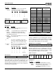
Master Volume Control (64h, R/W)
Bit Definitions:
0 0 0 0 Enable 3-D Reset 0 0
7 6 5 4 3 2 1 0
Bits Name Description
7:4 0 Reserved. Always write 0.
3 Enable
3-D
1 = Enable 3-D effect.
0 = Disable 3-D effect (effect unit bypassed).
2 Reset 1 = Release from reset.
0 = Reset 3-D effect.
0 0 Reserved. Always write 0.
0 0 Reserved. Always write 0.
0 0 3-D level
7 6 5 4 3 2 1 0
Bits Name Description
7:6 0 Reserved. Always write 0.
5:0 3-D level 0 is minimum effect; 3Fh is maximum effect.
0 1:Mute Left master volume
7 6 5 4 3 2 1 0
0 1:Mute Right master volume
7 6 5 4 3 2 1 0
0 1:Mute Left volume counter
7 6 5 4 3 2 1 0
0 1:Mute Right volume counter
7 6 5 4 3 2 1 0
Split
mode
MPU-401
int mask
Count
by 3
Read-only HMV
int request
Mode
HMV int
mask
Disable SB Pro master
vol emulation
7 6 5 4 3 2 1 0
Bits Name Description
7 Split
mode
1 = Split counter registers from volume registers
and access them independently.
0 = Slave counter and volume registers together.
6 MPU-
401 int
mask
This bit is AND'ed with the MPU-401 interrupt
request. If it is low, the MPU-401 interrupt request
stays low. This bit is cleared by hardware reset.
5 Count
by 3
1 = Count up and down by 3 for each push of Up
or Down buttons.
0 = Count up and down by 1 for each push of Up
or Down buttons.
This bit is cleared by hardware reset.
4 Read-
only
HMV int
request
Read-only interrupt request from hardware
volume event.