
Specifications

60 SAM0023-122898 ESS Technology, Inc.
ES1869 DATA SHEET
REGISTERS
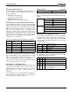
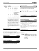
Serial Mode Output Control (44h, R/W)
Bit Definitions:
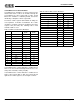
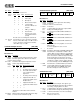
Serial Mode Analog Control (46h, R/W)
Bit Definitions:
Serial Mode Control (48h, R/W)
Bit Definitions:
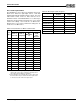
6:4 Record
source
select
Selects the record source.
Record source is unchanged in Serial mode.
3:0 Record
level
For microphone source, specifies record gain
from 0 to +22.5 dB in steps of 1.5 dB. For other
sources, specifies record level from -6 dB to
+16.5 dB in steps of 1.5 dB.
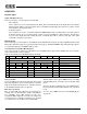
Master volume override Serial mode output select Master volume
7 6 5 4 3 2 1 0
Bits Name Description
7 Master
volume
override
1 = Master Volume during Serial mode is taken
from this register rather than from the Master
Volume registers.
6:4 Serial
mode
output
select
Determines what signal is input to the master
volume stage during Serial mode.
* Overrides record monitor and record mute
features.
3:0 Master
volume
Master Volume during Serial mode if bit 7 is high.
0 is mute and 15 is maximum (0 dB).
Bits Name Description
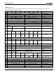
Bit 6 Bit 5 Bit 4 Record Source
0 0 0 Line
0 0 1 Aux A (CD)
0 1 0 Microphone
0 1 1 Master volume inputs
1 0 0 L channel: Mic
R channel: Master vol
(L+R)/2 *
1 0 1 AOUT_L / AOUT_R
1 1 0 Record mixer
1 1 1 Record source is dis-
connected from filters
(muted)
Bit 6 Bit 5 Bit 4 Master Volume Input
0 0 0 Mute
0 0 1 No change from normal op
0 1 0 First audio channel DAC
only – playback mixer
bypassed *
0 1 1 No change from normal op
1 0 0 Playback mixer with 1st
audio channel DAC set to 0
dB attenuation *
1 0 1 Playback mixer with 1st
audio channel DAC muted *
1 1 0 ----
1 1 1 ----
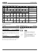
Analog control
override
Music
mixer test
Left
ADC
Right
ADC
Mono x
FDXO
enable
FDXI
enable
7 6 5 4 3 2 1 0
Bits Name Description
7 Analog
control
override
1 = bits 5:0 of this register take effect during
Serial mode.
0 = bits 5:0 never take effect.
6 Music
mixer
test
Test feature.
1 = Music DAC mixer inputs are replaced with
AUXB_L and AUXB_R inputs.
5 Left
ADC
1 = Left channel combined ADC and DAC is in
ADC mode.
0 = Left channel combined ADC and DAC is in
DAC mode.
4 Right
ADC
1 = Right channel combined ADC and DAC is in
ADC mode.
0 = Right channel combined ADC and DAC is in
DAC mode.
3 Mono 1 = Mono record, mono playback, or mono full-
duplex modes.
0 = Stereo playback or stereo record.
2 – No function.
1 FDXO
enable
Provided for backward compatibility with ES1868.
If Serial mode is enabled, bit 7 and bit 1 of this
register (46h) are high, and bit 6 of register 48h is
low (serial reset inactive), then the MONO_OUT
pin is selected to be a buffered output of the right
channel CIN_R pin (assumed to be used as a
mono DAC output in Serial mode). This condition
overrides the settings of mixer register 7Dh, bits
2:1, which normally select the MONO_OUT state.
0 FDXI
enable
If Serial mode is enabled and bit 5 (left channel
used for ADC) and bit 0 are high, then the left
channel filter input is the MONO_IN pin rather
than the normally selected record source.
SE
Two’s
comp
Serial
reset
Enable
ES689/ES69x
intfc
Active-low
sync
DSP test
mode
Enable 1st
DMA in
SMODE
0
7 6 5 4 3 2 1 0
Bits Name Description
7 SW SE 1 = Enable DSP serial port. This signal is syn-
chronized with DCLK input rising edge. If DCLK is
not running, changing SE has no effect.
6 Two’s
comp
1 = Data format is signed, two's complement format.
0 = Data format is unsigned (offset binary) format.
5 Serial
reset
1 = DSP serial interface reset. Resets left/right
flags for stereo modes.
0 = Release from reset.