
Specifications

6 SAM0023-122898 ESS Technology, Inc.
ES1869 DATA SHEET
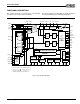
PIN DESCRIPTION
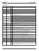
PIN DESCRIPTION
Name Number I/O Description
A[11:0] 99,100,1,2,6:4,
10:8,97,98
I Address inputs from the ISA bus.
VDDD 3,57,80 I Digital supply voltage (5 V ± 10%).
GNDD 7,24,52,77 I Digital ground.
AEN 11 I Active-low address enable from the ISA bus.
D[7:0] 19:12 I/O ISA bidirectional data bus.
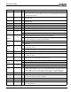
PSEL
20
I Selects the PnP ROM device used:
0 Internal ROM
1 93LC66 – 512 x 8, 9 address bits
SECS I/O Serial EEPROM CS. This is an input pin during RESET.
SEDO
21
I Input connected to the data output pin of the external PnP serial EEPROM.
VOLDN I Active-low volume decrease button input with internal pull-up (shared with the SEDO pin).
SEDI
22
O Output connected to the data input pin of the external PnP serial EEPROM.
VOLUP I Active-low volume increase button input with internal pull-up (shared with the SEDI pin).
MUTE
23
I Active-low mute toggle button input with internal pull-up (shared with the SECLK pin).
SECLK O External serial EEPROM clock output for PnP.
MONO_OUT 25 O Mono output with source select and volume control (including mute). This pin can drive an
external 5k ohm AC load.
MONO_IN 26 I Mono input to mixer and ADC. This pin has an internal pull-up to CMR.
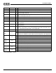
T(A-D) 27:30 I/O Joystick timer pins. These pins connect to the X-Y positioning variable resistors for the two
joysticks.
SW(A-D) 31:34 I Active-low joystick switch setting inputs. These pins have an internal pull-up resistor. The
joystick port is typically at address 201h.
AUXB_L 35 I Auxiliary B input left. AUXB_L has an internal pull-up resistor to CMR. Normally intended for
connection to an external music synthesizer or other line-level source.
AUXB_R 36 I Auxiliary B input right. AUXB_R has an internal pull-up resistor to CMR. Normally intended
for connection to an external music synthesizer or other line-level source.
AUXA_L 37 I Auxiliary A input left. AUXA_L has an internal pull-up resistor to CMR. Normally intended for
connection to an internal or external CD-ROM analog output.
AUXA_R 38 I Auxiliary A input right. AUXA_R has an internal pull-up resistor to CMR. Normally intended
for connection to an internal or external CD-ROM analog output.
CMR 39 O Common mode buffered reference output (2.25 V ± 5%). This pin should be bypassed to
analog ground with a 47 µF electrolytic capacitor with a 0.1 µF capacitor in parallel.
MIC 40 I Microphone input. MIC has an internal pull-up resistor to CMR.
GNDA 41 I Analog ground.
CAP3D 42 I Bypass capacitor to analog ground for 3-D effects.
VDDA 43 I Analog supply voltage (5 V ± 5%). Must be greater than or equal to VDDD - 0.3 V.
FOUT_R 44 O Filter output right. FOUT_R is AC-coupled externally to CIN_R to remove DC offsets. This
output has an internal series resistor of about 5k ohms. A capacitor to analog ground on this
pin can be used to create a low-pass filter pole that removes the switching noise introduced
by the switched-capacitor filter.