
Specifications

52 SAM0023-122898 ESS Technology, Inc.
ES1869 DATA SHEET
PROGRAMMING THE ES1869
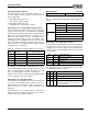
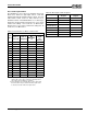
3. Clocks and counters: registers 70h, 72h, 74h and 76h:
Register 70h: Sample Rate Generator
Register 72h: Filter Clock Divider
Registers 74h/76h: Audio 2 Transfer Count Reload
register low/high, two's complement
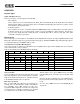
4. Initialize and configure DAC: register 7Ah.
Register 7Ah:
Bit 2: set high for signed data, low for unsigned.
Bit 1: set high for stereo, low for mono.
Bit 0: set high for 16-bit samples, low for 8-bit.
5. Enable IRQ channel, register 7Ah:
Register 7Ah: Audio 2 Control 2 register.
Bit 6 unmasks channel 2 IRQ.
6. Configure system interrupt controller and DMA
controller.
7. To start DMA:
Set bits 1:0 of register 78h high.
8. Delay approximately 100 milliseconds to allow analog
circuits to settle, then enable the Audio 2 DAC
playback volume, register 7Ch.
9. During DMA
For Auto-Initialize transfers, read Audio_Base+Eh to
clear the interrupt request. Do not send any other
commands to the ES1869 at interrupt time.
For Normal mode, initialize the system DMA controller
with the address and count of the next block to transfer.
Update the ES1869 Transfer Count registers if the
count is changed. To start the next transfer, clear bits
1:0 of register 78h, then set the bits high again.
To stop a DMA transaction in progress, clear bit 0 of
register B8h. To stop a DMA transaction after the
current auto-initialize block is finished, clear bit 4 of
register 78h, wait for the interrupt, and then clear bits
1:0 of register 78h.
10.After DMA is finished:
Restore the system interrupt controller and DMA
controller to their idle state. Monitor the FIFO Empty
status flag in port Audio_Base+Ch to be sure data
transfer is completed. A delay of 25 milliseconds is
required to let the filter outputs settle to DC-levels, then
disable the Audio 2 DAC input to the mixer.
11.Finally:
Issue another software reset to the ES1869 to initialize
the appropriate registers.
Full-Duplex DMA Mode (No DSP Serial Port)
The ES1869 supports stereo full-duplex DMA. In full-
duplex (FD) mode, a second audio channel has been
added to the ES1869. The second audio channel is
programmed through mixer registers. The CODEC is used
for recording and the Audio 2 DAC is used for playback.
1. Program the first audio channel as in “Extended Mode
Audio 1 ADC Operation” on page49. Extended mode
registers A1h and A2h define the sample rate and filter
frequency for both record and playback.
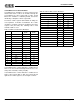
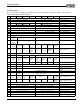
2. Program the second audio channel. Mixer registers
74h and 76h are set to the two's complement DMA
transfer count. The second audio channel supports
both Auto-Initialize and Normal modes. The playback
buffer in system memory does not have to be the same
size as the record buffer. When the DMA transfer count
rolls over to zero, it can generate an interrupt that is
independent of the interrupt generated by the first
audio channel.
If the record and playback buffers are the same size, then
a single interrupt can be used. Program the DMA Transfer
Count Reload registers (A4h, A5h, 74h, and 76h) are
programmed with the same value for both channels.
Enable the second audio channel before enabling the
record channel. For example, assume there are two half-
buffers in a circular buffer. When the record channel
completes filling the first half, it generates an interrupt. To
ensure that the playback channel is not accessing the first
half at the time of the interrupt, start the playback channel
first. It has a 32-word FIFO that fills quickly through DMA.
Programming the ES1869 Mixer
The ES1869 has a set of mixer registers that is backward
compatible with the Sound Blaster Pro. However, some of
the registers can be accessed in an “extended” or
“alternate” way, providing for greater functionality.
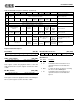
Writing and Reading Data from the Mixer Registers
There are two I/O addresses used by the mixer:
Audio_Base+4h is the address port; Audio_Base+5h is
the data port. In the Sound Blaster Pro, Audio_Base+4h is
write only, while Audio_Base+5h is read/write.
Writing Data to the ES1869 Mixer Registers
To set a mixer register, write its address to
Audio_Base+4h, then write the data to Audio_Base+5h.
Reading Data from the ES1869 Mixer Registers
To read the register, write its address to Audio_Base+4h,
then read the data from Audio_Base+5h.