
Specifications

ESS Technology, Inc. SAM0023-122898 51
ES1869 DATA SHEET
PROGRAMMING THE ES1869
14.After DMA is finished:
Restore the system interrupt controller and DMA
controller to their idle state.
15.Finally:
Issue another software reset to the ES1869 to initialize
the appropriate registers. This returns the ES1869 to
the DAC direction and turns off the record monitor.
Extended Mode Programmed I/O Operation
The REP OUTSB instruction of the 80x86 family transfers
data from memory to an I/O port specified by the DX
register. The REP INSB instruction is the complementary
function. Use ES1869 port Audio_Base+Fh for block
transfers.
I/O transfers to FIFO are nearly identical to the DMA
process, except that an I/O access to port Audio_Base+Fh
replaces the DMA cycle. Some differences are described
here.
To program in this mode it is useful to understand how the
FIFO Half-Empty flag generates an interrupt request. An
interrupt request is generated on the rising edge of the
FIFO Half-Empty flag. This flag can be polled by reading
port Audio_Base+Ch. The meaning of this flag depends
on the direction of the transfer:
DAC FIFOHE flag is set high if 0-127 bytes in FIFO
ADC FIFOHE flag is set high if 128-256 bytes in FIFO
Therefore, for DAC operations, an interrupt request is
generated when the number of bytes in the FIFO changes
from >= 128 to < 128. This indicates to the system
processor that 128 bytes can be safely transferred without
over-filling the FIFO. Before the first interrupt can be
generated, the FIFO needs to be primed, or filled, with
more than 128 bytes. Keep in mind that data may be taken
out of the FIFO while it is being filled by the system
processor. If that is the case, there may never be >= 128
bytes in the FIFO unless somewhat more than 128 bytes
is transferred. Polling the ES1869 FIFOHE flag to be sure
it goes low in the interrupt handler (or when priming the
FIFO) and perhaps sending a second block of 128 bytes
is a solution to this problem.
For ADC, the interrupt request is generated when the
number of bytes in the FIFO changes from < 128 to >=
128, indicating that the system processor can safely read
128 bytes from the FIFO. Before the first interrupt can be
generated, the FIFO should be emptied (or mostly so) by
reading from Audio_Base+Fh and polling the FIFOHE
flag. It is not safe to use FIFO reset bit 1 of port
Audio_Base+6h indiscriminately to clear the FIFO,
because it may get ADC data out-of-sync.
As in DMA mode, bit 0 of register B8h enables transfers
between the system and the FIFO inside the ES1869.
NOTE: The ES1869 is designed for I/O block transfer up
to a ISA bus speed of 8.33 MHz.
Programmed I/O DAC Operation
Programmed I/O DAC operation is done just as explained
under “Extended Mode Audio 1 DAC Operation” on
page48 with the following exceptions:
• In step 3, programming register B9h is
unnecessary.
• In step 6, leave bits 7:5 of register B2h low. Set bit
5 of register B1h high to enable an interrupt on FIFO
half-empty transitions. Keep bit 6 of register B1h
low.
• In step 8, in addition to setting bit 0 of register B8h
high, send the REP OUTSB command.
Programmed I/O ADC Operation
Programmed I/O ADC operation is done just as explained
under “Extended Mode Audio 1 ADC Operation” on
page49 with the following exceptions:
• In step 3, programming register B9h is
unnecessary.
• In step 6, leave bits 7:5 of register B2h low. Set bit
5 of register B1h high to enable an interrupt on FIFO
half-empty transitions. Keep bit 6 of register B1h
low.
• In step 8, in addition to setting bit 0 of register B8h
high, send the REP OUTSB command.
Second Audio Channel DAC Operation
Follow the steps below to program the second audio
channel for DAC operation.
1. Reset
Write 3h to port Audio_Base+6h, instead of 1h as in
Compatibility mode. Bit 1 high specifically clears the
FIFO. The remainder of the software reset is identical
to Compatibility mode. On reset the playback mixer
volume for the second audio channel is set to zero,
register 7Ch. This masks any pops that might occur
during the setup process.
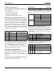
2. Program transfer type: register 78h:
Register 78h: set bit 4 low for Normal DMA mode, high
for Auto-Initialize DMA mode.
Bits 7:6 00: Single Transfer DMA
Bits 7:6 01: Demand Transfer DMA:
2 bytes per DMA request.
Bits 7:6 10: Demand transfer DMA:
4 bytes per DMA request.
Bits 7:6 11: Demand transfer DMA:
8 bytes per DMA request.