
Specifications

50 SAM0023-122898 ESS Technology, Inc.
ES1869 DATA SHEET
PROGRAMMING THE ES1869
Register B8h: set bit 3 high to program the CODEC for
the ADC direction. Set bit 2 low for Normal DMA mode,
high for Auto-Initialize DMA mode.
At this point the direction of the analog circuits is ADC
rather than DAC. Unless the recording monitor is
enabled, there will be no output from AOUT_L or
AOUT_R until the direction is restored to DAC.
Register A8h: read this register first to preserve the bits
and modify only bits 3, 1, and 0:
Bits 1:0 10: Mono
Bits 1:0 01: Stereo
Bit 3 0: Disable Record Monitor for now
Register B9h:
Bits 1:0 00: Single Transfer DMA
Bits 1:0 01: Demand Transfer:
2 bytes per DMA request
Bits 1:0 11: Demand Transfer:
4 bytes per DMA request
6. Clocks and counters: registers A1h, A2h, A4h and A5h:
Register A1h: Sample Rate Clock Divider. Set bit 7
high for sample rates greater than 22 kHz.
Register A2h: Filter Clock Divider.
Registers A4h/A5h: Audio 1 Transfer Count Reload
register low/high, two's complement
7. Delay 100 milliseconds to allow analog circuits to
settle.
8. Enable Record Monitor if desired:
Register A8h bit 3 = 1: Enable Record Monitor
(optional).
9. Initialize and configure ADC: register B7h. See Table
17. The first command sent to register B7h initializes
the DAC and prevents pops.
Register B7h: programs the FIFO (16-bit/8-bit, signed/
unsigned, stereo/mono).
10.Enable/select DMA channel and IRQ channel,
registers B1h and B2h:
Register B1h: Interrupt Configuration register.
Verify that bits 4 and 6 are high. Clear bits 7 and 5.
Register B2h: DRQ Configuration register:
Verify that bits 4 and 6 are high. Clear bits 7 and 5.
11.Configure system interrupt controller and DMA
controller.
12.To start DMA:
Set bit 0 of register B8h high. Leave other bits
unchanged.
13.During DMA
For Auto-Initialize transfers, do not send any
commands to the ES1869 at interrupt time, except for
reading Audio_Base+Eh to clear the interrupt request.
For Normal mode, initialize the system DMA controller
with the address and count of the next block to transfer.
Update the ES1869 Transfer Count registers if the
count is changed. To start the next transfer, clear bit 0
of register B8h, then set it high again.
To stop a DMA transaction in progress, clear bit 0 of
register B8h. To stop a DMA transaction after the
current auto-initialize block is finished, clear bit 2 of
register B8h, wait for the interrupt, and then clear bit 0
of register B8h.
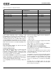
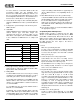
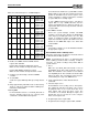
Table 17 Command Sequence for DMA Record
Mono Stereo 8-bits 16-bits Unsigned Signed Sequence
X X X Reg B7h = 51h,
Reg B7h = D0h
X X X Reg B7h = 71h,
Reg B7h = F0h
X X X Reg B7h = 51h,
Reg B7h = D4h
X X X Reg B7h = 71h,
Reg B7h = F4h
X X X Reg B7h = 51h,
Reg B7h = 98h
X X X Reg B7h = 71h,
Reg B7h = B8h
X X X Reg B7h = 51h,
Reg B7h = 9Ch
X X X Reg B7h = 71h,
Reg B7h = BCh