
Specifications

ESS Technology, Inc. SAM0023-122898 49
ES1869 DATA SHEET
PROGRAMMING THE ES1869
6. Enable/select DMA channel and IRQ channel,
registers B1h and B2h:
Register B1h: Interrupt Configuration register.
Make sure bits 4 and 6 are high. Clear bits 7 and 5.
Register B2h: DRQ Configuration register.
Make sure bits 4 and 6 are high. Clear bits 7 and 5.
7. Configure system interrupt controller and DMA
controller.
8. To start DMA:
Set bit 0 of register B8h high while preserving all other
bits.
9. Delay approximately 100 milliseconds to allow analog
circuits to settle, then enable the Audio 1 DAC input to
mixer with command D1h.
10.During DMA
For Auto-Initialize transfers, read Audio_Base+Eh to
clear the interrupt request. Do not send any other
commands to the ES1869 at interrupt time.
For Normal mode, initialize the system DMA controller
with the address and count of the next block to transfer.
Update the ES1869 Transfer Count registers if the
count is changed. To start the next transfer, clear bit 0
of register B8h, then set it high again.
To stop a DMA transaction in progress, clear bit 0 of
register B8h. To stop a DMA transaction after the
current auto-initialize block is finished, clear bit 2 of
register B8h, wait for the interrupt, and then clear bit 0
of register B8h.
11.After DMA is finished:
Restore the system interrupt controller and DMA
controller to their idle state. Monitor the FIFO Empty
status flag in port Audio_Base+Ch to be sure data
transfer is completed. A delay of 25 milliseconds is
required to let the filter outputs settle to DC-levels, then
disable the first DMA DAC input to the mixer with
command D3h.
12.Finally:
Issue another software reset to the ES1869 to initialize
the appropriate registers.
Extended Mode Audio 1 ADC Operation
Follow the steps below to program the first audio channel
for Extended mode ADC operation:
NOTE: In Extended mode, there is no Automatic Gain
Control (AGC) performed while recording. If AGC is
necessary, use 16-bit recordings and perform AGC in
system software.
1. Reset
Write 3h to port Audio_Base+6h instead of 1h as in
Compatibility mode. Bit 1 high specifically clears the
FIFO. The remainder of the software reset is identical
to Compatibility mode. Reset disables the Audio 1 DAC
input to the mixer. This is intended to mask any pops
created during the setup of the DMA transfer.
2. Send command C6h to enable Extended mode
commands.
3. Select the input source:
The ES1869 has four recording sources: microphone,
line, auxiliary A, and mixer. The mixer source can be
the playback mixer or the record mixer. Bits 4:3 of
mixer register 7Ah selects the mixer source. The
record mixer is the default. Microphone input is the
default after any reset. Select the source using the
mixer control register 1Ch.
4. Program input volume register B4h.
5. Program direction and type: registers B8h, and A8h:
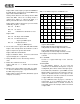
Table 16 Command Sequences for DMA Playback
Mono Stereo 8-bits 16-bits Unsigned Signed Sequence
X X X Reg B6h = 80h,
Reg B7h = 51h,
Reg B7h = D0h
X X X Reg B6h = 00h,
Reg B7h = 71h,
Reg B7h = F0h
X X X Reg B6h = 80h,
Reg B7h = 51h,
Reg B7h = D4h
X X X Reg B6h = 00h,
Reg B7h = 71h,
Reg B7h = F4h
X X X Reg B6h = 80h,
Reg B7h = 51h,
Reg B7h = 98h
X X X Reg B6h = 00h,
Reg B7h = 71h,
Reg B7h = B8h
X X X Reg B6h = 80h,
Reg B7h = 51h,
Reg B7h = 9Ch
X X X Reg B6h = 00h,
Reg B7h = 71h,
Reg B7h = BCh