
Specifications

46 SAM0023-122898 ESS Technology, Inc.
ES1869 DATA SHEET
PROGRAMMING THE ES1869
For stereo transfers, set the timer divider to twice the
per-channel sample rate. The maximum stereo
transfer rate for 8-bit data is 22 kHz per channel; so for
this case, program the first timer divider as if you were
transferring data at 44 kHz mono. The maximum stereo
transfer rate for 16-bit data is 11 kHz per channel.
4. Set the block size. Only use this command (48h) with
High-Speed DMA transfer modes (commands 90h and
91h).
5. Configure the system interrupt controller and system
DMA controller.
6. Start DMA.
Start the DMA transfer by sending the command for the
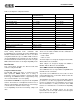
desired transfer type and data length. The
uncompressed modes are shown in Table 14. See
Table 26 for a description of the commands in addition
to the commands for DMA transfers of compressed
data.
7. Delay approximately 100 milliseconds to allow the
analog circuits to settle, then enable the Audio 1 DAC
input to mixer with command D1h.
8. During DMA.
For Auto-Initialize mode, it is not necessary to send any
commands to the ES1869 at interrupt time, except to
read Audio_Base+Eh to clear the interrupt request.
For Normal mode, initialize the system DMA controller
with the address and count of the next block size if it
changes. Use command 48h. To start the next transfer,
use command D4h.
To stop DMA after the current auto-initialize block is
finished, use command D0h.
Commands such as D1h and D3h, which control the
Audio 1 DAC mixer input enable/disable status, and
command D0h, which suspends DMA, are acceptable
to send during DMA transfers. These commands can
only be sent during certain windows of opportunity. See
“Stereo DMA Transfers in Compatibility Mode” on
page44.
9. After DMA is finished, restore the system interrupt
controller and DMA controller to their idle state. Monitor
the FIFO Empty status flag in port Audio_Base+Ch to
be sure that data transfer is completed. Delay 25
milliseconds to let the filter outputs settle to DC-levels,
then disable the Audio 1 DAC input to the mixer with
command D3h.
10.Issue another software reset to the ES1869 to initialize
the appropriate registers.
Compatibility Mode ADC Operation
ES1869 analog circuitry is switched from the DAC
direction to the ADC direction by the first direct or DMA
mode ADC command (2xh). Discard the first 25 to 100
milliseconds of samples because pops might occur in the
data due to the change from the DAC to ADC direction. In
the ADC direction the voice input to the mixer is
automatically muted.
1. Reset
Write 1h to port Audio_Base+6h.
To play a new sound without resetting the ES1869
beforehand, when the status of the analog circuits is
not clear, mute the input to the mixer with command
D3h to prevent pops.
2. Select the input source using register 0Ch
Sound Blaster Pro has three recording sources:
microphone, line, and auxiliary A (CD). Microphone
input is the default source after any reset.
The ES1869 has four recording sources: microphone,
line, auxiliary A (CD), and mixer. Use mixer register
1Ch to choose the additional source.
3. Program the input volume.
The selected source passes through an input volume
stage that can be programmed with 16 levels of gain
from 0 to +22.5 dB in steps of 1.5 dB. In 8-bit
recordings (other than High-Speed mode), the volume
stage is controlled by the ES1869 firmware for the
purposes of automatic gain control (AGC). In 16-bit
recordings as well as High-Speed mode 8-bit
recordings, the input volume stage is controllable from
application software. Use command DDh to change
the input volume level from 0 to 15. The reset default is
mid-range, 8.
4. Enable stereo mode (optional).
Set bit 1 of mixer register 0Eh high. Use only DMA
mode. Clear bit 1 of mixer register 0Eh after the ADC
transfer.
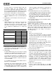
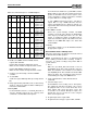
Table 14 Uncompressed DAC Transfer Modes
DAC DMA Transfer Mode Data Length Command
Direct 8-bit 10h
16-bit 11h
DMA mode Normal 8-bit 14h
16-bit 15h
High-Speed 8-bit 91h
DMA mode Auto-Initialize 8-bit 1Ch
16-bit 1Dh
High-Speed 8-bit 90h