
Specifications

ESS Technology, Inc. SAM0023-122898 45
ES1869 DATA SHEET
PROGRAMMING THE ES1869
For 16-bit data, the ES1869 expects DMA transfers to be
a multiple of 4, with repeating groups in the order:
1. left low byte
2. left high byte
3. right low byte
4. right high byte
ES1869 Data Formats (Extended Mode and Audio 2)
There are eight formats available from the combination of
the following three options:
• Mono or stereo
• 8-bit or 16-bit
• Signed or unsigned
For stereo data, the data stream always alternates
channels in successive samples: first left, then right. For
16-bit data, the low byte always precedes the high byte.
Sending Commands During DMA Operations
It is useful to understand the detailed operation of sending
a command during DMA.
The ES1869 uses the Audio 1 FIFO for DMA transfers to/
from the CODEC. When the FIFO is full (in the case of
DAC) or empty (in the case of ADC), DMA requests are
temporarily suspended and the Busy flag (bit 7 of port
Audio_Base+Ch) is cleared. This opens a window of
opportunity to send a command to the ES1869. Commands
such as D1h and D3h which control the Audio 1 DAC mixer
input enable/disable status, and command D0h, which
suspends or pauses DMA, are acceptable to send during
this window.
The ES1869 chip sets the Busy flag when the command
window is no longer open. Application software must send
a command within 13 microseconds after the Busy flag
goes high or the command will be confused with DMA
data. Sending a command within the command window is
easy if polling is done with interrupts disabled.
As an example of sending a command during DMA,
consider the case where the application wants to send
command D0h in the middle of a DMA transfer. The
application disables interrupts and polls the Busy flag.
Because of the FIFO and the rules used for determining
the command window, it is possible for the current DMA
transfer to complete while waiting for the Busy flag to clear.
In this event, the D0h command has no function, and a
pending interrupt request from the DMA completion is
generated.
The interrupt request can be cleared by reading port
Audio_Base+Eh before enabling interrupts or having a
way of signaling the interrupt handler that DMA is inactive
so that it does not try to start a new DMA transfer.
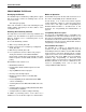
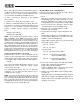
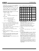
Figure 21 shows timing considerations for sending a
command.
Figure 21 Command Transfer Timing
Compatibility Mode Programming
This section describes Compatibility mode programming.
Compatibility Mode DAC Operation
1. Reset
Write 1h to port Audio_Base+6h.
To play a new sound without resetting the ES1869
beforehand, when the status of the analog circuits is
not clear, mute the input to the mixer with command
D3h to prevent pops.
2. Enable stereo mode (optional).
Set bit 1 of mixer register 0Eh high. Use only DMA
mode. Clear bit 1 of mixer register 0Eh after the DAC
transfer.
3. Set sample rate and filter clock.
Use commands 40h or 41h to set the sample rate and
filter clock divider. To set the filter clock to be
independent from the sample rate, use command 42h
in addition to 40h or 41h.
BUSY FLAG
POLL BUSY
WRITE COMMAND OK
WRITE COMMAND NOT OK
13 µsec