
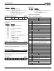
Specifications

ESS Technology, Inc. SAM0023-122898 33
ES1869 DATA SHEET
PNP CONFIGURATION AND REGISTERS
Bit Definitions:
LDN 1: Audio Device
This device actually supports three functions: audio, FM,
and MPU-401. Audio requires sixteen I/O locations, one
interrupt which is shared with MPU-401, and two DMA
channels. FM requires four I/O locations. MPU-401
requires two I/O locations.
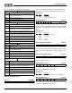
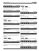
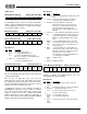
Activate (30h, R/W)
After reset or after a 1 is written to the reset bit in the card’s
configuration control bit, the default for this register is 0.
Bit Definitions:
I/O Range Check (31h, R)
This register verifies that the I/O range assigned to a
logical device does not conflict with the I/O range used by
another device.
Bit Definitions:
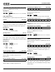
Audio Processor I/O Base Address (60h, R/W)
I/O base address of audio processor, bits 11:8.
Sixteen locations.
Audio Processor I/O Base Address (61h, R/W)
I/O base address of audio processor, bits 7:4.
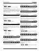
FM Alias I/O Base Address (62h, R/W)
I/O base address of FM alias, bits 11:8. Four locations.
FM Alias I/O Base Address (63h, R/W)
I/O base address of FM alias, bits 7:2.
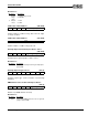
MPU-401 I/O Base Address (64h, R/W)
I/O base address of MPU-401, bits 11:8. (MPU-401 may
also be accessible through LDN 3). Two locations.
MPU-401 I/O Base Address (65h, R/W)
I/O base address of MPU-401, bits 7:2.
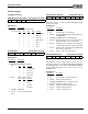
Interrupt Request Channel 1 Select (70h, R/W)
Interrupt request channel 1 select.
Bit Definitions:
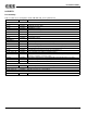
Interrupt Request Type Select 1 (71h, R)
Interrupt request type select 1. Returns 2 (low-to-high
transition).
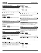
Interrupt Request Channel 2 Select (72h, R/W)
Interrupt request channel 2 select.
Bit Definitions:
Bits Name Description
2:0 Data Select which channel is in use for DMA 1.
0 0 0 0 0 0 0 Activate
7 6 5 4 3 2 1 0
Bits Name Description
0 Activate 1 = Activate.
0 = Deactivate (default).
0 0 0 0 0 0 Enable range check Pattern select
7 6 5 4 3 2 1 0
Bits Name Description
1 Enable
range
check
1 = Enable range check.
0 = Disable.
0 Pattern
select
1 = 55h.
0 = AAh.
0 0 0 0 A[11:8]
7 6 5 4 3 2 1 0
A[7:4] 0 0 0 0
7 6 5 4 3 2 1 0
0 0 0 0 A[11:8]
7 6 5 4 3 2 1 0
A[7:2] 0 0
7 6 5 4 3 2 1 0
0 0 0 0 A[11:8]
7 6 5 4 3 2 1 0
A[7:2] 0 0
7 6 5 4 3 2 1 0
0 0 0 0 Data
7 6 5 4 3 2 1 0
Bits Name Description
3:0 Data Select which interrupt used for channel 1 IRQ.
0 0 0 0 0 0 1 0
7 6 5 4 3 2 1 0
0 0 0 0 Data
7 6 5 4 3 2 1 0
Bits Name Description
3:0 Data Select which interrupt used for channel 2 IRQ.