
Specifications

ESS Technology, Inc. SAM0023-122898 25
ES1869 DATA SHEET
PERIPHERAL INTERFACING
MONO_IN and MONO_OUT
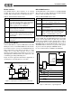
MONO_IN is a line-level analog input. MONO_IN is an
input to the playback mixer and the record mixer. The
mixer volumes are controlled by mixer registers 6Dh
(playback) and 6Fh (record).
Alternately, MONO_IN can be mixed with AOUT_L and
AOUT_R after the master volume stage. Bit 0 of mixer
register 7Dh, when high, enables MONO_IN to be mixed
directly (unity gain) with AOUT_L and AOUT_R.
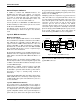
A third use of MONO_IN is as an input to the left channel
ADC in full-duplex DSP serial port mode. In this
application, MONO_IN is typically a line-level microphone
input (external preamp). MONO_IN can be selected as an
input in serial port mode by setting bits 6 and 7 of mixer
register 42h high. MONO_IN as an ADC input bypasses
the recording source select and record volume stages.
MONO_IN directly drives the left channel switched-
capacitor filter. The output of the switched-capacitor filter
is FOUT_L, which is AC-coupled externally to CIN_L, the
left channel ADC input.
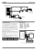
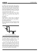
MONO_OUT is a line-level mono output. During power-
down or during opamp calibration, MONO_OUT is held at
CMR (as are AOUT_L and AOUT_R) by an internal, high-
impedance resistor divider. MONO_OUT can be selected
from among four sources by bits 2 and 1 of mixer register
7Dh.
Normally bits 2:1 are both zero, so that MONO_OUT is
muted.
When bit 2 is 0 and bit 1 is 1, MONO_OUT is a buffered
version of input pin CIN_R. CIN_R is typically the right
channel DAC output, filtered by the first channel switched-
capacitor filter. If the right channel is used for ADC, CIN_R
will be the right channel ADC input. MONO_OUT can be
used in this application as digitized audio playback
through the first channel DMA, right channel DAC.
When bit 2 is 1 and bit 1 is 0, MONO_OUT is a buffered
version of the second channel, right channel DAC. In this
case, the second channel DMA can play digitized audio
through MONO_OUT.
When bit 2 is 1 and bit 1 is 1, MONO_OUT is a buffered
version of a mono mix of the record level stage left and
right outputs. This gives the utmost flexibility in the source
or sources of MONO_OUT. The record source select and
record levels can be programmed to generate any
combination of sources and volumes for MONO_OUT.
Spatializer
®
VBX™ Audio Processor
The ES1869 incorporates an embedded Spatializer
®
VBX™ stereo audio processor provided by Desper
Products, Inc., a subsidiary of Spatializer Audio Laboratories,
Inc. It is positioned between the output of the playback
mixer and the master volume controls and it produces a
wider perceived stereo effect.
The 3-D effect is enabled by register 50h bit 3. The amount
of effect is controlled by directly programming 3-D Level
register 52h.
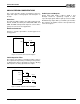
Hardware and Master Volume Control
Three external pins, VOLUP, VOLDN, and MUTE can be
connected to external momentary switches to ground to
implement hardware master volume controls. Pressing
one of these buttons produces a low signal to one of the
inputs and thereby changes the master volume.
In one mode the MUTE input can be replaced by the state
where both VOLUP and VOLDN inputs are low.
The up and down buttons produce a single step change in
volume when they are first pressed. If these buttons are
held down, they enter a fast-scrolling mode. The single
step change can be either one volume unit (.75 dB) or
three volume units (2.25 dB). In scrolling mode, the step
change is always one volume unit.
The three inputs have debounce circuitry within the
ES1869. Hold each input low for 40 milliseconds or more
for it to be recognized as a valid button press. Hold each
input high for 40 milliseconds or more between button
presses. A software option allows the debounce time to be
reduced from 40 milliseconds to 10 microseconds.
Normally the hardware volume controls directly change
the master volume registers and produce an interrupt at
each change. However, the ES1869 can be programmed
so that the hardware volume controls do not directly
change the master volume registers. This is called “split
mode”, in which the hardware volume control counters are
split from the master volume registers. Pressing a
hardware volume control button changes the hardware
volume counters and produces an interrupt. The host
software can read the hardware volume counters and
update the master volume registers as needed. Split mode
is enabled by bit 7 of mixer register 64h.
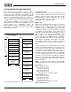
Mixer Register 7Dh
MONO_OUT Source
Bit 2 Bit 1
0 0 Mute (CMR)
0 1 First channel filter output
(actually CIN_R pin)
1 0 Second channel DAC, right channel
1 1 Mono mix of record level stage outputs