
Specifications

ESS Technology, Inc. SAM0023-122898 23
ES1869 DATA SHEET
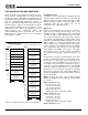
PERIPHERAL INTERFACING
General-Purpose I/O Device
In addition to modem and CD-ROM interfaces, the
ES1869 Plug and Play logic supports one general-
purpose I/O device. The GPO0 output can be configured
to provide an active-high chip-select output when this
device is accessed. The General-Purpose device can
decode 1, 2, 4, 8, or 16 consecutive addresses.
It is also possible to use GPI/GPO1 as a DMA channel for
the General-Purpose device if these pins are not used for
the Modem or CD-ROM device.
The GPI pin can also be used as an interrupt source for
the General-Purpose device if the pin is not otherwise
used.
Joystick / MPU-401 Interface
MPU-401 UART Mode
There are two separate MIDI interfaces in the ES1869.
The Sound Blaster compatible command set and a MPU-
401 “UART mode” compatible serial port. MPU-401 is a
superior method of MIDI serial I/O because it does not
interfere with DAC or ADC Sound Blaster commands.
Both methods of serial I/O share the same MSI and MSO
pins. The MPU-401 interface consists of separate 8-byte
FIFOs for receive and transmit.
By default after hardware reset, the MPU-401 interface is
disabled. It must be configured using PnP register 30h of
LDN3, which is described in “LDN 3: MPU-401 Device” on
page34.
MPU-401 requires an interrupt channel for MIDI receive.
This interrupt should be selected using PnP register 70h
of LDN3. It should be different than the interrupt selected
for audio DMA interrupts.
If MPU-401 is enabled, a low-level signal on pin MSI
prevents power-down and causes automatic wake-up if
the ES1869 is powered down. Likewise, power-down is
prevented if a byte is currently being received or
transmitted.
Temporarily disabling MPU-401 using PnP register 30h of
LDN3 (if MPU-401 is its own device) or PnP register 30h
of LDN1 (if MPU-401 is part of the audio device) acts as a
reset to the FIFOs.
Joystick / MIDI External Interface
The joystick portion of the ES1869 reference design is
identical to that on a standard PC game control adaptor or
game port. The PC compatible joystick can be connected
to a 15-pin D-sub connector. It supports all standard PC
joystick-compatible software. If the system already has a
game card or port, either remove the game card or disable
the joystick port in the reference design by removing the
joystick enable jumper. Disabling the joystick port does not
affect its use as a MIDI port.
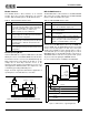
If multiple joysticks are required, use a joystick conversion
cable. This cable uses a 15-pin D-sub male connector on
one end, and two 15-pin D-sub female connectors on the
other end. All signals on this cable have direct pin-to-pin
connection, except for pins 12 and 15. On the male
connector, pins 12 and 15 should be left without
connection. On the female connectors, pin 15 is internally
connected to pin 8, and pin 12 is internally connected to
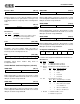
pin 4. The dual joystick and MIDI port take up only one slot
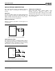
in the system, leaving room for other cards. Figure 14
shows the dual joystick/MIDI connector configuration.
Figure 14 Dual Joystick/MIDI Connector
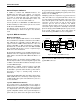
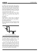
Figure 15 shows the MIDI serial interface adaptor from the
joystick/MIDI connector.
+5V
Button
Button
MIDI OUT
MIDI IN
GND
Button
Button
Joystick B Joystick A
X-axis
Y-axis
X-axis
Y-axis
1
2
3
4
5
6
7
8
9
10
11
12
13
14
15