
Specifications

22 SAM0023-122898 ESS Technology, Inc.
ES1869 DATA SHEET
PERIPHERAL INTERFACING
Modem Interface
The ES1869 allows a direct interface to an external
modem. There are four pins dedicated for an external
modem. Table 9 identifies pins in the Modem interface.
Modem Operating Modes
If the modem DSP also requires a DMA channel, the GPI/
GPO1 pins can be used for DRQ/-DACK from the modem.
The modem can also connect to the ES1869 through the
DSP serial interface. This allows the modem to set the
sample rate for both chips and have access to the
microphone and speaker for speakerphone or voice-over-
data applications. DSP determines the sample rate of the
serial link by generating FSR/FSX pulses.
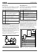
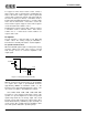
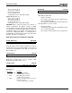
Figure 12 shows a typical modem interface application, a
speakerphone or modem with voice-over-data.
Figure 12 Speakerphone or Modem w/ Voice-Over-Data
IDE CD-ROM Interface
The ES1869 allows a direct interface to an IDE CD-ROM
drive. There are four pins dedicated for an IDE CD-ROM
interface. Table 10 identifies these pins.
In most cases, the IDE interface does not use DMA. If it
must use DMA, then the GPO1/GPI pair (pins 91 and 92)
can be used for this purpose. In this case, these pins
would not be available for other external devices such as
a modem/audio processor. Also, typically only one of the 4
DRQ/DACK pairs of the ES1869 would be connected to a
16-bit DMA channel. This does not give the PnP system
any choice about assigning the CD DMA channel.
It is not recommended to use DMA for the CD-ROM.
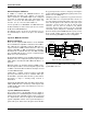
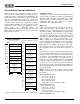
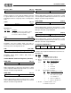
Figure 13 IDE Interface – Typical Application
Table 9 External Modem Interface Pins
Pin Description
MMCSB Output from the ES1869 to an external modem chip
select, active-low. The address space is determined
by the PnP configuration. The Modem device uses
eight consecutive addresses, with the base
address, typically one of the COM ports.
MMIRQ Interrupt request from the Modem device. This
signal is mapped to an IRQ output on the ES1869,
based on the PnP configuration.
MMIEB Modem interrupt enable input. Active-low when the
Modem interrupt is enabled. High when the Modem
interrupt request is disabled. Generated from the
Modem UART.
GPCS User-defined general-purpose chip select output.
If selected by the PnP logic and based on the PnP
configuration.
SpeakerMicrophone
ES1869
ADC DAC
Serial #2
Modem DSP
Modem
Data
Serial #1
CODEC
ISA Bus
FIFO
Telephone Line
Table 10 IDE CD-ROM Interface Pins
Pin Description
CDIRQ Interrupt request from CD-ROM. Internally routed
to one of the six IRQ ISA outputs (A-F).
CDCSB0 Active-low decode output for eight command block
registers. 24 mA driver.
CDCSB1 Active-low decode output for two control block reg-
isters. 24 mA driver.
CDENBL Active-low decode output for external 74LS245
transceiver that buffers the least 8 bits of the ISA
data bus. This pin is active-low when CDCSB0,
CDCSB1, or CD DMA -DACK is active-low.
ES1869
RSTB
CDCSB0
CDCSB1
CDIRQ
CDENBL
IDE CONNECTOR
-DACK
SD[15:8]
IOCHRDY
-IOCS16
SA[2:0]
-IOW
-IOR
DIR
EN
SD[7:0]
74LS245
ISA CONNECTOR