
Specifications

ESS Technology, Inc. SAM0023-122898 19
ES1869 DATA SHEET
PERIPHERAL INTERFACING
PERIPHERAL INTERFACING
I
2
S Serial Interface
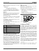
Three input pins, IISDATA, IISCLK, and IISLR, are used
for a serial interface between an external device and a
stereo DAC within the ES1869. These inputs can be left
floating or connected to ground if the serial interface is not
used.
Typical applications of the I
2
S serial interface are MPEG
audio or digital CD audio.
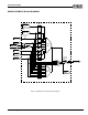
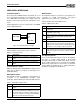
Figure 8 I
2
S Implementation in ES1869
Table 6 identifies the three pins in the I
2
S interface.
I
2
S Serial Interface Timing
Within the ES1869, IISLR and IISDATA are sampled on the
rising edge of IISCLK. See Figure 31 and Figure 32 for
detailed I
2
S timing.
Wavetable Interface
The ES1869 contains a synchronous serial interface for
connection to an ES689/ES69x wavetable music
synthesizer. Table 7 identifies pins in the wavetable interface.
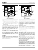
DSP Interface
The ES1869 contains a synchronous serial interface for
connection to a DSP serial interface. The typical
application for this interface is a speakerphone.
Table 8 identifies pins in the DSP interface.
DSP Operating Modes
There are two DSP data transfer modes for the ES1869.
The state of a single switch internal to the ES1869
determines which mode is enabled. This switch can route
the first audio channel to the second audio channel DAC.
When the first audio channel is routed to the second audio
channel DAC, Telegaming mode is enabled. Otherwise
the DSP is operating in its default mode.
Table 6 I
2
S Interface Pins
Pin Description
IISLR Left/right strobe for I
2
S interface. Input with pull-
down.
IISDATA Serial data for I
2
S interface. Input with pull-down.
IISCLK Serial shift clock for I
2
S interface. Input with pull-
down.
Table 7 Wavetable Interface Pins
Pin Description
MCLK Serial clock from external ES689/ES69x music syn-
thesizer.
MSD Serial data from external ES689/ES69x music syn-
thesizer. When both MCLK and MSD are active, the
stereo DACs that are normally used by the FM syn-
thesizer are acquired for use by the external ES689/
ES69x. The normal FM output is blocked.
PC CARD
IISDATA
IISCLK
IISLR
ES1869
Table 8 DSP Interface Pins
Pin Description
SE Active-high signal from an external DSP to enable
serial mode.
DCLK Data clock. The rate can vary, but a typical value is
2.048 MHz (8 kHz x 256).
DX Data transmit. Active output when data is being trans-
mitted serially from the ES1869, otherwise high-
impedance.
DR Serial data input.
FSX Frame sync transmit. FSX is either active-high or
active-low based on bit 3 of mixer register 48h. The
FSX pulse is a request from the external DSP to begin
transmission of 8 or 16 bits of data out of pin DX.
FSR Frame sync receive. FSR is either active-high or
active-low, based on bit 3 of mixer register 48h. The
FSR pulse signals the arrival of 8 or 16 bits of data to
pin DR.