
Specifications

ESS Technology, Inc. SAM0023-122898 17
ES1869 DATA SHEET
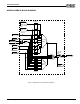
INTERRUPTS
INTERRUPTS
There are seven interrupt sources in the ES1869, shown in Table 4.
Interrupt sources are mapped to one of the six interrupt
output pins through the PnP registers. Zero, one, or more
interrupts can map to any given pin. Each PnP pin is
assigned to an ISA interrupt channel number by Vendor-
Defined Card-Level PnP registers 20h, 21h, and 22h.
These registers are automatically loaded from the 8-byte
header in the PnP configuration data.
Each interrupt pin can be in either an active or high-
impedance state.
If a given interrupt pin has one or more sources assigned
to it, and one or more of those sources is activated
(register 30h, bit 0), then the interrupt pin is active; that is,
it always drives high or low. An exception is the Modem
interrupt, which can be deactivated if input MMIEB is high
or if the Modem device is not active. Each interrupt also
has one or more mask bits that are AND'ed with the
interrupt request.
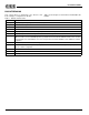
Interrupt Status Register
Port Config_Base+6h of the configuration device can be
read to quickly find out which ES1869 interrupt sources
are active. The bits are:
Table 4 ES1869 Interrupt Sources
Interrupt Source Description
Audio 1 An interrupt used for the first DMA channel (Sound Blaster compatible DMA, Extended mode DMA, and
Extended mode programmed I/O), as well as Sound Blaster-compatible MIDI receive. Controller register B1h
controls use of this interrupt for Extended mode DMA and programmed I/O. This interrupt request is cleared by
hardware or software reset, or an I/O read from port Audio_Base+0Eh. The interrupt request can be polled by
reading from port Audio_Base+0Ch. The Audio 1 interrupt is assigned to an interrupt channel by PnP register
70h of LDN 1.
Audio 2 An optional interrupt for the second DMA channel. The ES1869 can operate in full-duplex mode using two
DMA channels. However, since the second DMA channel must share the same sample rate as the first DMA
channel, it is not necessary to use a separate interrupt for the second DMA channel. The Audio 2 interrupt is
masked by bit 6 of mixer register 7Ah. It can be polled and cleared by reading or writing bit 7 of register 7Ah.
This interrupt is assigned to an interrupt channel by PnP register 72h of LDN 1.
Hardware Volume Hardware volume activity interrupt. This interrupt occurs when one of the three hardware volume controls
changes state. Bit 1 of mixer register 64h is the mask bit for this interrupt. The interrupt request can be polled
by reading bit 3 of register 64h. The interrupt request is cleared by writing any value to register 66h. The Hard-
ware Volume interrupt is assigned to an interrupt channel by PnP register 27h. Typically this interrupt, if used,
is shared with an audio interrupt.
MPU-401 The MPU-401 interrupt occurs when a MIDI byte is received. It goes low when a byte is read from the MIDI
FIFO and goes high again quickly if there are additional bytes in the FIFO. The interrupt status is the same as
the Read-Data-Available status flag in the MPU-401 status register. The MPU-401 interrupt is masked by bit 6
of mixer register 64h. This interrupt is assigned to an interrupt channel in one of two ways. If the MPU-401 is
part of the audio device, then PnP register 28h is used to assign the MPU-401 interrupt. If the MPU-401 is its
own logical device, it can also be assigned to an interrupt by PnP register 70h of LDN 3. Both these methods
access the same physical register.
CD-ROM The source of the CD-ROM interrupt is the input pin CDIRQ.
Modem The source of the Modem interrupt is the input pin MMIRQ.
General-Purpose The source of the General-Purpose interrupt is the input pin GPI. If GPI is used for a DMA request for the
CD-ROM, Modem, or General-Purpose device, then this pin cannot be used as a general-purpose device
interrupt.
Table 5 Interrupt Status Bits in Config_Base+6h
Bit Description
0 Audio 1 interrupt request
1 Audio 2 interrupt request AND'ed with bit 6 of mixer
register 7Ah
2 Hardware volume interrupt request AND'ed with bit 1 of
mixer register 64h
3 MPU-401 receive interrupt request AND'ed with bit 6 of
mixer register 64h
4 CDIRQ input pin
5 MMIRQ input pin AND'ed with inverse of MMIEB input
6 GPI input pin