
Specifications

ESS Technology, Inc. SAM0023-122898 15
ES1869 DATA SHEET
DIGITAL AUDIO
DMA mode is used when programming the second audio
channel for transfers:
• DMA modes
– Normal (Single or Demand transfer)
– Auto-Initialize (Single or Demand transfer)
In addition, both DMA Normal mode and DMA Auto-
Initialize mode use Single or Demand transfer modes.
DMA Modes
DMA under the second audio channel supports both Nor-
mal and Auto-Initialize mode. In addition, Normal mode
and Auto-Initialize mode both support Single and
Demand transfer modes.
For a description of DMA mode including Normal DMA
mode and Auto-Initialize DMA mode, see “DMA Modes”
on page13.
For a description of Single and Demand transfer modes,
see “DMA Modes” on page14.
Audio 2 Related Mixer Registers
The following registers control DMA operations for the
second audio channel:
External DMA Sharing with Audio DMA
It is possible for an external DMA device to share a DMA
channel with audio DMA if they do not operate at the same
time, and if the respective Windows drivers can
communicate with each other. In this case, the external
DMA device does not request an audio channel in its
resource data. Instead, the Windows driver writes to the
PnP DMA register of the appropriate device to assign it to
the same DMA channel as one of the two audio channels.
Bits 4:2 of Vendor-Defined Card-Level register 26h can be
used to mask any of the three DMA sources (audio 1,
audio 2, and external). Use masking when DMA channels
are shared to be sure that only one device has access to
a given DMA channel at one time.
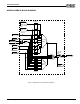
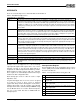
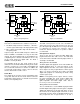
DRQ Latch Feature
DRQ latching is enabled when bit 7 of PnP Vendor-
Defined Card-Level register 25h is high.
If this feature is enabled, each of the four audio DRQs is
latched high until one of the following occurs:
• A DACK low pulse occurs while DRQ is low or goes low
due to a DACK pulse.
• A hardware reset occurs.
• 8-16 milliseconds elapse while DRQ is low.
Figure 7 DRQ Latch
First DMA Channel CODEC
The CODEC of the first audio channel cannot perform
stereo DAC and ADC simultaneously. It can either be a
stereo DAC, a stereo ADC, or a mono CODEC. After
reset, the CODEC is set up for DAC operations. Any ADC
command causes a switch to the ADC “direction,” and any
subsequent DAC command switches the converter back
to the DAC “direction.”
The DAC output is filtered and sent to the mixer. After
reset, input to the mixer from the first audio channel DAC
is muted to prevent pops. The ES1869 maintains a status
flag to determine if the input to the mixer from the first
audio channel DAC is enabled or disabled. Command D8h
returns the status of the flag (0h=disabled and
FFh=enabled). Use command D1h to enable input to the
mixer from the first audio channel DAC and command D3h
to disable the input.
To play a new sound without resetting beforehand, when
the status of the analog circuits is not clear, mute the input
to the mixer with command D3h, then set up DAC direction
and level using the direct-to-DAC command:
10h + 80h
Wait 25 milliseconds for the analog circuitry to settle
before enabling the voice channel with command D1h.
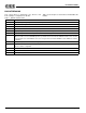
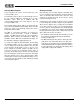
Table 3 Audio 2 Related Mixer Registers
Address Name
70h Audio 2 Sample Rate register
71h Audio 2 Mode register
72h Audio 2 Filter Clock Rate register
74h Audio 2 Transfer Count Reload register – low byte
76h Audio 2 Transfer Count Reload register – high byte
78h Audio 2 Control 1 register
7Ah Audio 2 Control 2 register
7Ch Audio 2 DAC Volume Control register
DRQ
125 Hz
-DACK
-RESET
OR
AND
S
R
DRQ Out
S
R