
Specifications


14 SAM0023-122898 ESS Technology, Inc.
ES1869 DATA SHEET
DIGITAL AUDIO
Before a DMA transfer, the application first programs the
DMA controller for the desired transfer size and address,
then programs the ES1869 with the same size
information. At the end of the transfer, the ES1869
generates an interrupt request, indicating that the current
block transfer is complete. The FIFO gives the application
program sufficient time to respond to the interrupt and
initiate the next block transfer.
The ES1869 supports both Normal DMA mode and Auto-
Initialize DMA mode.
Normal DMA Mode
In Normal mode DMA transfers, the DMA controller must
be initialized and the ES1869 commanded for every block
that is transferred.
Auto-Initialize DMA Mode
In Auto-Initialize mode, the DMA transfer is continuous, in
a circular buffer, and the ES1869 generates an interrupt
for the transition between buffer halves. In this mode the
DMA controller and ES1869 only need to be set up once.
High-Speed Mode
The ES1869 supports mono 8-bit DMA transfers at a rate
up to 44 kHz. Mono 16-bit transfers are supported up to a
rate of 22 kHz.
The special “High-Speed mode” allows 8-bit sampling up
to 44 kHz for ADC, using commands 98h (auto-initialize)
and 99h (normal). No automatic gain control (AGC) is
performed. The input volume is controlled with command
DDh.
DMA Transfers in Extended Mode
The first audio channel is programmed using the controller
registers internal to the ES1869. The commands written to
the controller registers are written to the chip through port
Audio_Base+Ch.
When programming the first audio channel for transfers,
one of the following modes can be used:
• Programmed I/O
• DMA modes
– Normal (Single or Demand transfer)
– Auto-Initialize (Single or Demand transfer)
In addition, both DMA normal mode and DMA auto-
initialize mode use Single transfer or Demand transfer
modes.
Programmed I/O
For some applications, DMA mode is not suitable or
available for data transfer, and it is not possible to take
exclusive control of the system for DAC and ADC
transfers. In these situations, use I/O block transfers within
an interrupt handler. The REP OUTSB instruction of the
80x86 family transfers data from memory to an I/O port
specified by the DX register. The REP INSB instruction is
the complementary function. Use ES1869 port
Audio_Base+Fh for block transfers.
I/O transfers to FIFO are nearly identical to the DMA
process, except that an I/O access to port Audio_Base+Fh
replaces the DMA cycle. For details about programmed
I/O operation see “Extended Mode Programmed I/O
Operation” on page51.
DMA Modes
Extended mode DMA supports both Normal and Auto-Ini-
tialize mode. In addition Normal mode and Auto-Initialize
mode both support Single and Demand transfer modes.
Single Transfer
One byte is transferred per DMA request.
Demand Transfer
To reduce the number of DMA requests necessary to
make a transfer, two or four bytes are transferred per DMA
request (DRQ). Using Demand transfer enables multiple
DMA acknowledges for each DMA request.
For a description of DMA mode including Normal DMA
mode and Auto-Initialize DMA mode see “DMA Modes” on
page13.
Extended Mode Audio 1 Controller Registers
The following registers control operation of the first audio
channel in Extended mode:
Data Transfers Using the Second Audio Channel
The second audio channel is programmed using mixer
registers 70h through 7Dh. The commands written to the
mixer registers are written to the chip through ports
Audio_Base+4h and Audio_Base+5h.
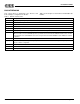
Table 2 Extended Mode Audio 1 Controller Registers
Address Name
A1h Audio 1 Sample Rate Generator register
A2h Audio 1 Filter Clock Divider register
A4h Audio 1 Transfer Count Reload register – low byte
A5h Audio 1 Transfer Count Reload register – high byte
B1h Legacy Audio Interrupt Control register
B2h Audio 1 DRQ Control register
B4h Input Volume Control register
B5h Audio 1 DAC Direct Access register – low byte
B6h Audio 1 DAC Direct Access register – high byte
B7h Audio 1 Control 1 register
B8h Audio 1 Control 2 register
B9h Audio 1 Transfer Type register